Method and device for time alignment calibration, event annotation and database generation

A time alignment and calibration method technology, applied in image data processing, special data processing applications, electrical components, etc.

Inactive Publication Date: 2018-11-02
BEIJING SAMSUNG TELECOM R&D CENT +1
View PDF5 Cites 7 Cited by
  • Summary
  • Abstract
  • Description
  • Claims
  • Application Information

AI Technical Summary

Problems solved by technology

Based on the above characteristics, DVS can solve problems that traditional visual sensors cannot solve, and also bring new challenges

Method used


Image

  • Method and device for time alignment calibration, event annotation and database generation
  • Method and device for time alignment calibration, event annotation and database generation
  • Method and device for time alignment calibration, event annotation and database generation

Examples


Embodiment Construction

[0052] Reference will now be made in detail to embodiments of the present invention, examples of which are illustrated in the accompanying drawings, wherein like numerals refer to like parts throughout. The embodiments are described below in order to explain the present invention by referring to the figures.

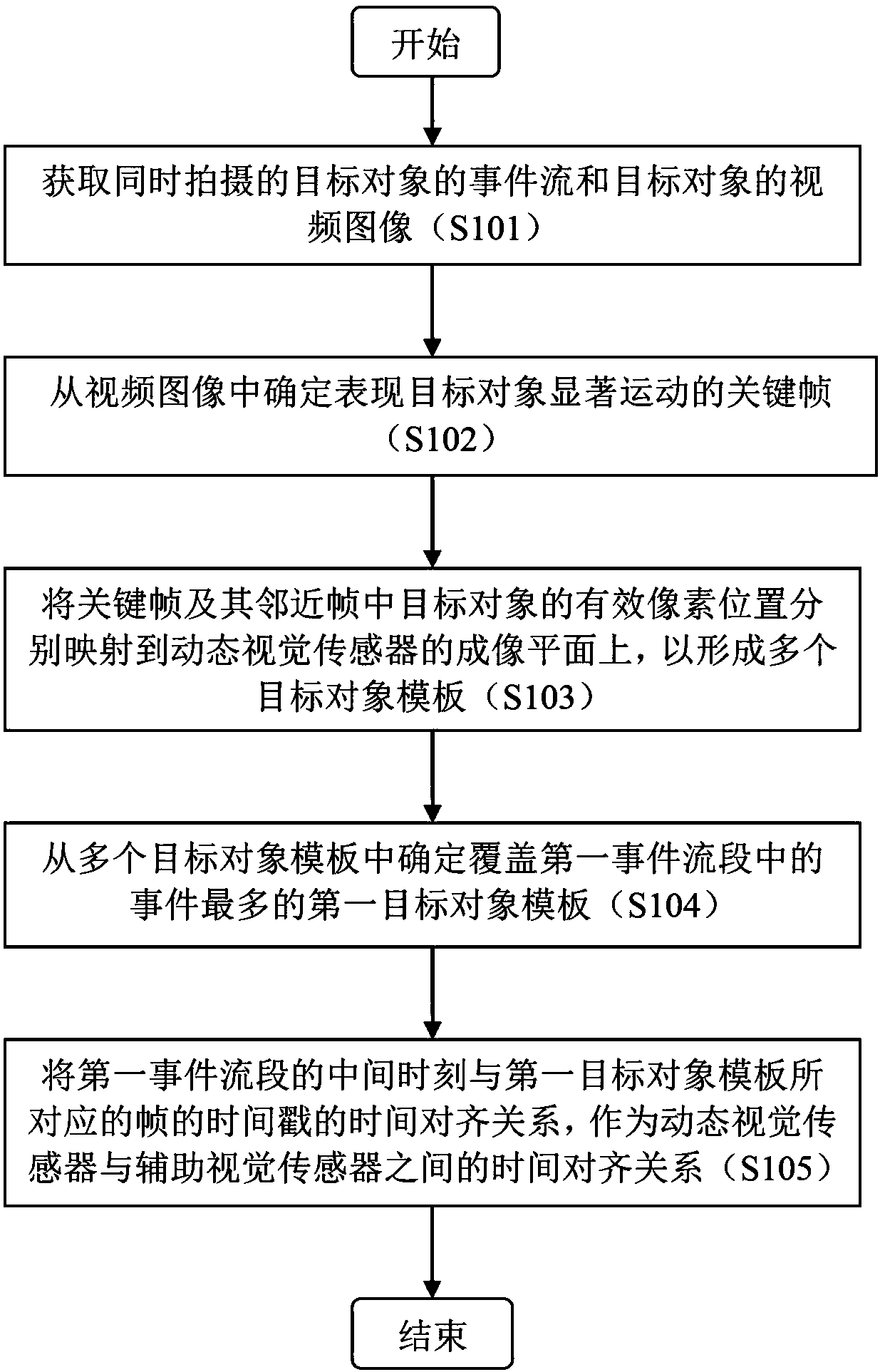
[0053] figure 1 A flowchart showing a time alignment calibration method according to an exemplary embodiment of the present invention.

[0054] refer to figure 1 , in step S101, acquire the event flow of the target object captured by the dynamic visual sensor and the video image of the target object captured by the auxiliary visual sensor. At the same time, the dynamic vision sensor and the auxiliary vision sensor are used to shoot the target object, and the event stream captured by the dynamic vision sensor and the video image captured by the auxiliary vision sensor are obtained.

[0055] It should be understood that the auxiliary vision sensor may be various types o...


PUM


Abstract

The invention provides a method and device for time alignment calibration, event annotation and database generation. The time alignment calibration method comprises the following steps: (A) acquiringan event stream of a target object shot by a dynamic vision sensor and a video image of the target object shot by an auxiliary vision sensor; (B) determining a key frame for representing obvious movement of the target object from a video image; (C) respectively mapping an effective pixel location of the target object in the key frame and an effective pixel location of the target object in the adjacent frame of the key frame to an imaging plane of the dynamic vision sensor, thereby forming multiple target object templates; (D) determining a first target object template covering the most eventsin the first event stream section from multiple target object templates; and (E) taking the time alignment relation of the middle moment of the first event stream section and the timestamp of the frame corresponding to the first target object template as the time alignment relation between the dynamic vision sensor and the auxiliary vision sensor.

Description

technical field [0001] The present invention generally relates to the field of dynamic vision sensors (Dynamic vision sensor, DVS), and more specifically, relates to a time alignment calibration method and device, an event labeling method and device, and a database generation method and device. Background technique [0002] Different from traditional frame-based visual sensors, DVS is a continuous imaging visual sensor in the time domain, and its time resolution can reach 1us. The output of DVS is a series of events (event), including the horizontal coordinate, vertical coordinate, polarity and time stamp (timestamp) of the event on the imaging plane. At the same time, DVS is a differential imaging sensor that only responds to changes in light. Therefore, its energy consumption is lower than that of ordinary vision sensors, and its light sensitivity is higher than that of ordinary vision sensors. Based on the above characteristics, DVS can solve problems that traditional vi...

Claims


Application Information

Patent Timeline
Patent Type & Authority Applications(China)
IPC IPC(8): G06T7/80G06T7/20G06V10/10G06V10/147
CPCG06T7/80G06T7/20G06T2207/10016G06T2207/30196G06T7/38G06T2207/10028G06V20/44G06V20/40G06V20/46G06V10/147G06V10/10G06V10/751G06F16/7867H04N7/181G06T7/248G06T7/292H04N5/04
Inventor 刘伟恒邹冬青石峰李佳柳贤锡禹周延王强李贤九朴根柱
Owner BEIJING SAMSUNG TELECOM R&D CENT
Why Eureka
Try Eureka