
A Multifunctional Fault Current Active Regulation Current Limiting System

A fault current and multi-functional technology, applied in the field of electric power, can solve the problems that the parameters of series reactors should not be too large, waste grid power, and low reuse rate, so as to improve device utilization and operation economy, and protect power system equipment And load safety, improve the effect of voltage compensation depth

Active Publication Date: 2020-08-04
CHANGSHA UNIVERSITY OF SCIENCE AND TECHNOLOGY
View PDF3 Cites 0 Cited by
  • Summary
  • Abstract
  • Description
  • Claims
  • Application Information

AI Technical Summary

Problems solved by technology

However, the busbar series reactance can only realize the fault current limiting function. The reactor is connected in series in the grid for a long time, which wastes the power of the grid, and the parameters of the series reactor should not be too large, resulting in insufficient current limiting effect; while other bridge current limiter devices are complex The utilization rate is low, the cost is high, and the general current limiting technical solution cannot improve the power quality

Method used


Image

  • A Multifunctional Fault Current Active Regulation Current Limiting System
  • A Multifunctional Fault Current Active Regulation Current Limiting System
  • A Multifunctional Fault Current Active Regulation Current Limiting System

Examples


Embodiment Construction

[0014] In order to make the purpose, technical solutions and advantages of the embodiments of the present invention clearer, the technical solutions in the embodiments of the present invention will be clearly and completely described below in conjunction with the drawings in the embodiments of the present invention. Obviously, the described embodiments It is a part of embodiments of the present invention, but not all embodiments. Based on the embodiments of the present invention, all other embodiments obtained by persons of ordinary skill in the art without creative efforts fall within the protection scope of the present invention.

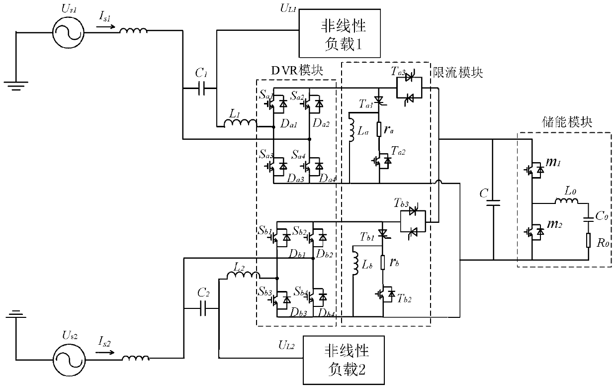
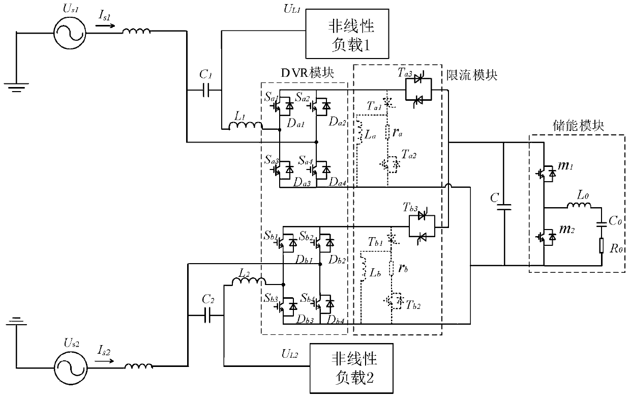
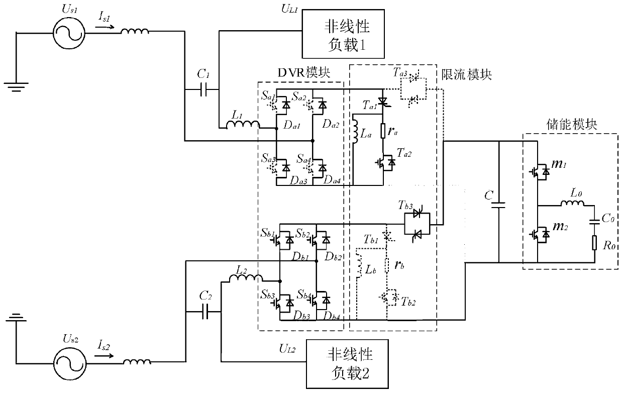
[0015] figure 1 It is a schematic structural diagram of a multifunctional fault current active regulation and current limiting system according to an embodiment of the present invention, as shown in figure 1 As shown, the system includes: a first filtering module, a first dynamic voltage compensation module, a first current limiting module, an en...


PUM


Abstract

The embodiment of the invention provides a multifunctional fault current active regulation current-limiting system. One end of a first filtering module is connected with one phase of a to-be-controlled power grid by a first inductor; one end of a first dynamic voltage compensation module is connected with a first end of a first current-limiting module; the other end of the first dynamic voltage compensation module is connected with a second end of the first current-limiting module; both ends of a voltage stabilization capacitor are respectively connected with a third end of the first current-limiting module and a second end of the first current-limiting module; an energy storage module is respectively connected with both ends of the voltage stabilization capacitor; if the to-be-controlledpower grid normally operates, the first current-limiting module is turned off, and dynamic voltage compensation is carried out on the to-be-controlled power grid by the first dynamic voltage compensation module. According to the invention, a short-circuit current under a fault that a short circuit occurs to a single feeder or short circuits simultaneously occur to both feeders can be effectively inhibited; voltage rising, falling and three-phase voltage unbalance dynamic compensation on double feeders are implemented, the voltage compensation depth is improved, and a fault overcurrent is inhibited.

Description

technical field [0001] The embodiments of the present invention relate to the field of electric power technology, and in particular to a multi-functional fault current active regulation and current limiting system. Background technique [0002] With the development of the national economy, the rapid growth of the load of my country's power system has led to the continuous increase of the short-circuit power and short-circuit current of the power grid, which is very harmful to the safe and stable operation of the power system; nonlinear devices and impacts widely used in industry Loads are likely to cause grid current and voltage waveform distortion, and the sensitive load on the user side of the distribution network is gradually increasing, and people's requirements for power quality are becoming more stringent. Therefore, limiting short-circuit current, improving the safety and reliability of power system operation, and providing high-quality electric energy to loads have be...

Claims


Application Information

Patent Timeline
Patent Type & Authority Patents(China)
IPC IPC(8): H02H9/02H02J3/12H02J3/26
CPCH02H9/02H02J3/12H02J3/26Y02E40/50
Inventor 姜飞涂春鸣李印宜郭祺吴震宇
Owner CHANGSHA UNIVERSITY OF SCIENCE AND TECHNOLOGY
Learn More