
Heat collection tube gas charging device

An inflatable device and heat collecting tube technology, applied in the field of heat collecting tubes, can solve the problems of large air chamber space, waste of gas, and difficult to take out pipelines, etc.

Pending Publication Date: 2018-10-30
SHANDONG ELECTRIC POWER CONSTR NO 2
View PDF5 Cites 0 Cited by
  • Summary
  • Abstract
  • Description
  • Claims
  • Application Information

AI Technical Summary

Problems solved by technology

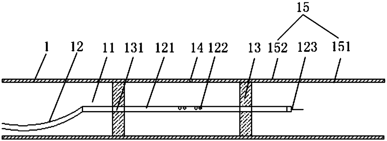
[0004] The existing heat collecting tube inflating device achieves air intake by blocking both ends of the pipe. The disadvantage is that the space of the air chamber is too large, which wastes gas, or measures 10-15cm on both sides of the weld to seal, and carry out from one side. Inflate, and this results in a small space in the air chamber and long pipelines are not easy to take out

Method used


Image

  • Heat collection tube gas charging device

Examples


Embodiment Construction

[0022] The technical solutions of the present invention will be clearly and completely described below in conjunction with the accompanying drawings. Apparently, the described embodiments are some of the embodiments of the present invention, but not all of them. Based on the embodiments of the present invention, all other embodiments obtained by persons of ordinary skill in the art without making creative efforts belong to the protection scope of the present invention.

[0023] In the description of the present invention, it should be noted that the terms "center", "upper", "lower", "left", "right", "vertical", "horizontal", "inner", "outer" etc. The indicated orientation or positional relationship is based on the orientation or positional relationship shown in the drawings, and is only for the convenience of describing the present invention and simplifying the description, rather than indicating or implying that the referred device or element must have a specific orientation, ...


PUM


Abstract

The invention relates to the field of heat collection tubes, in particular to a heat collection tube gas charging device. The heat collection tube gas charging device comprises a heat collection tube.The heat collection tube comprises a plurality of gas chambers and a gas inlet device. The multiple gas chambers are linearly arranged and are sealed relative to one another. The gas inlet device comprises a gas inlet pipe. The gas inlet device penetrates through all the gas chambers. Exhaust holes are formed in the gas inlet pipe and are used for releasing gas to corresponding gas chambers. Withthe heat collection tube gas charging device, the purposes that gas is saved, operation is facilitated, the efficiency is improved, the gas charging quality of the heat collection tube especially theroot part is guaranteed, argon is saved, manual work is reduced, and the construction efficiency is improved are achieved.

Description

technical field [0001] The invention relates to the field of heat collecting tubes, in particular to a heat collecting tube charging device. Background technique [0002] As one of the clean energy sources with the best development prospects, solar energy has an increasingly wide application range and scale. The research and application of photothermal power generation corresponding to solar energy is also in the stage of urgent development. In China, the research and application of photothermal power generation The technology is still in its infancy. [0003] As more and more CSP projects are put into commercial operation in Europe, America and other countries, the domestic CSP technology research and application will gradually mature. With its unique environmental protection advantages, solar thermal power generation will surely develop rapidly, and the matching construction tools must be further improved to meet the needs of engineering construction. [0004] The existi...

Claims


Application Information

Patent Timeline
Patent Type & Authority Applications(China)
IPC IPC(8): F24S80/00
CPCY02E10/40
Inventor 黄维强邓同喜齐永平张学发单国军于水雨
Owner SHANDONG ELECTRIC POWER CONSTR NO 2
Learn More