Continuous wax dotting shaft

A technology of spotting wax and wax wheel, which is applied in the direction of electrolytic coating, electrophoretic plating, coating, etc., which can solve the problems of high intensity of wax sealing work, and achieve the effect of compact structure, low failure rate and high precision

Active Publication Date: 2018-10-30
KUNSHAN SOKAY AUTOMATION TECH CO LTD
View PDF13 Cites 0 Cited by
  • Summary
  • Abstract
  • Description
  • Claims
  • Application Information

AI Technical Summary

Problems solved by technology

However, for partial sealing of complex products in batches, the work intensity of sealing wax appears to be large, and more reliable, high-efficiency, and low-cost components are needed to assist partial sealing of wax

Method used


Image

  • Continuous wax dotting shaft
  • Continuous wax dotting shaft
  • Continuous wax dotting shaft

Examples


Embodiment Construction

[0031] Below in conjunction with specific embodiment, content of the present invention is described in further detail:

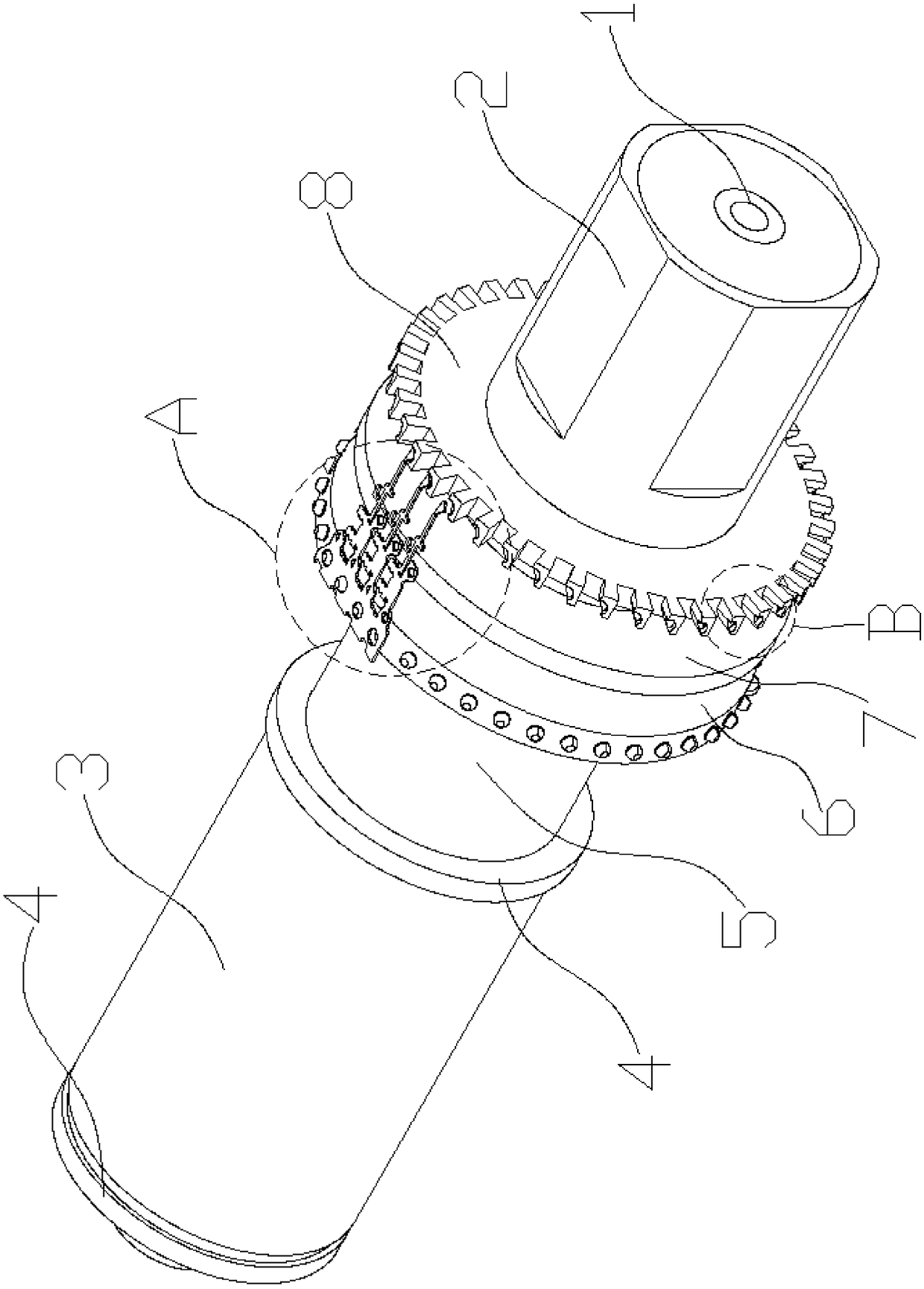
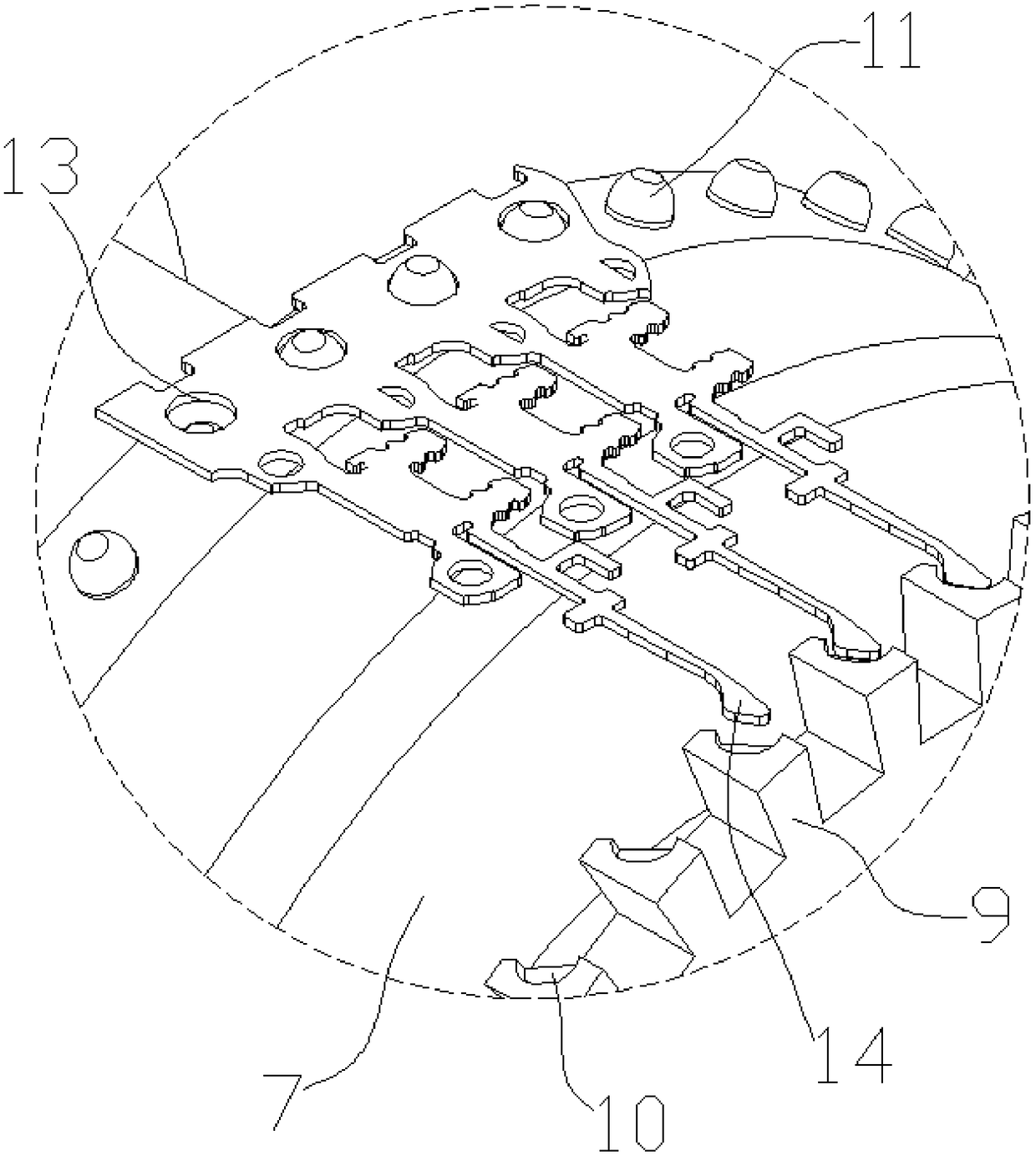
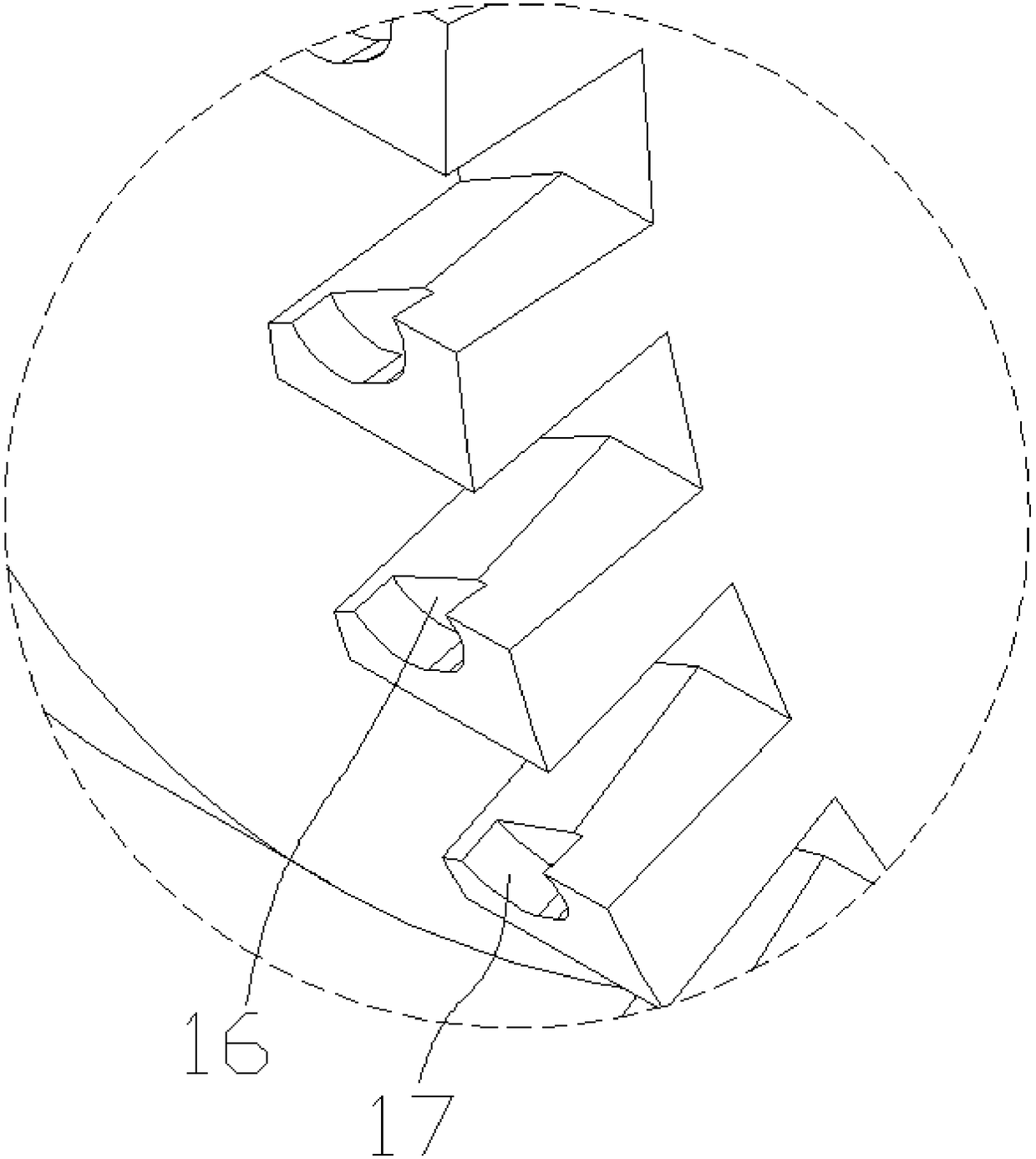
[0032] In order to achieve the purpose of the present invention, a continuous waxing shaft includes: a positioning wheel 6, which has several radially protruding positioning bumps 11 on its circumferential surface, and the positioning bumps 11 are inserted into the circular holes 13 of the material belt 12, The driving material belt 12 is horizontally conveyed; the wax sticking wheel 8 is arranged in parallel with the positioning wheel 6 and is integrally connected by the central shaft. Radial teeth 9, each radial tooth 9 is equipped with a sunken wax holding tank 10, wax liquid 15 is stained on the inner wall of the wax holding tank 10, the sticking wax wheel 8 rotates coaxially with the positioning wheel 6, and the wax liquid 15 sticks Attached to the material belt 12; the heater 1; nested in the central axis, the wax liquid 15 on the sticky wax wheel 8 is...


PUM


Abstract

The invention discloses a continuous wax dotting shaft which comprises a locating wheel, a wax sticking wheel and a heater. The circumference face of the locating wheel is provided with a plurality oflocating protruding points protruding in the radial direction. The locating protruding points are inserted into round holes of a material belt and drive the material belt to be conveyed horizontally.The wax sticking wheel and the locating wheel are arranged in parallel and are connected integrally through a center shaft. The self axis of the wax sticking wheel coincides with that of the locatingwheel. The wax sticking wheel is provided with protruding radial teeth. Each radial tooth is provided with a sunken wax containing groove. Wax liquid adheres to the inner wall of each wax containinggroove. The wax sticking wheel and the locating wheel rotate coaxially to enable the wax liquid to adhere to the material belt. The heater is nested in the center shaft and controls the wax liquid onthe wax sticking wheel within the liquid state temperature. A coaxial bearing wheel is arranged between the locating wheel and the wax sticking wheel and is provided with a circumference face. By theadoption of the continuous wax dotting shaft, a plurality of wheels on one shaft are utilized for precisely conveying the strip-shaped material belt, bearing the material belt and carrying out local wax sealing on the material belt, the structure cost is low, and the wax sealing efficiency is high.

Description

technical field [0001] The invention relates to equipment in the field of electrophoresis, in particular to a continuous waxing shaft. Background technique [0002] The field of continuous electrophoresis is sometimes applied to special sealing wax products, and the melting point of the wax is used to selectively perform electrophoresis or non-electrophoresis on the locality of the product. However, for partial wax sealing of batches of complex products, the work intensity of wax sealing is large, and more reliable, high-efficiency, and low-cost components are needed to assist partial wax sealing. Contents of the invention [0003] The problem to be solved by the present invention is to provide a continuous wax dispensing shaft, which uses several wheels on one shaft to carry out accurate transmission, support and local wax sealing for strip-shaped material belts, with low structural cost and high wax sealing efficiency. [0004] In order to solve the above problems, the ...

Claims


Application Information

Patent Timeline
Patent Type & Authority Applications(China)
IPC IPC(8): C25D13/20
CPCC25D13/20
Inventor 张文标
Owner KUNSHAN SOKAY AUTOMATION TECH CO LTD
Why Eureka
Try Eureka