
Three-dimensional reconstruction method and device uniting rigid motion and non-rigid deformation

A rigid motion and three-dimensional reconstruction technology, which is applied in the fields of computer vision and computer graphics, can solve the problems of scanning result errors, slow speed, and expensive counterfeiting, and achieve the effects of improving real-time performance, strong scalability, and simple and easy implementation

Active Publication Date: 2018-10-26
TSINGHUA UNIV +1
View PDF3 Cites 19 Cited by
  • Summary
  • Abstract
  • Description
  • Claims
  • Application Information

AI Technical Summary

Problems solved by technology

However, the acquisition of high-quality 3D models is usually achieved by expensive laser scanners or multi-camera array systems. Although the accuracy is high, there are also some obvious disadvantages: first, the object is required to remain absolutely still during the scanning process, and the tiny Moving will lead to obvious errors in the scanning results; second, counterfeiting is expensive, and it is difficult to popularize it in the daily life of ordinary people. It is often used in large companies or national statistics departments
Third, the speed is slow. It often takes at least 10 minutes to several hours to rebuild a 3D model, and the cost of rebuilding a dynamic model sequence is even greater.
But this reconstruction method needs to obtain the key frame 3D model of the object in advance
On the other hand, although the existing frame-by-frame dynamic fusion surface reconstruction methods can achieve dynamic 3D reconstruction without templates, they only use non-rigid surface deformation methods, and the robustness of tracking reconstruction is low.

Method used


Image

  • Three-dimensional reconstruction method and device uniting rigid motion and non-rigid deformation
  • Three-dimensional reconstruction method and device uniting rigid motion and non-rigid deformation
  • Three-dimensional reconstruction method and device uniting rigid motion and non-rigid deformation

Examples


Embodiment Construction

[0050] Embodiments of the present invention are described in detail below, examples of which are shown in the drawings, wherein the same or similar reference numerals designate the same or similar elements or elements having the same or similar functions throughout. The embodiments described below by referring to the figures are exemplary and are intended to explain the present invention and should not be construed as limiting the present invention.

[0051] The following describes the 3D reconstruction method and device for combining rigid motion and non-rigid deformation according to the embodiments of the present invention with reference to the accompanying drawings. .

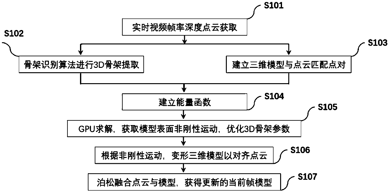
[0052] figure 1 It is a flowchart of a three-dimensional reconstruction method combining rigid motion and non-rigid deformation according to an embodiment of the present invention.

[0053] like figure 1 As shown, the 3D reconstruction method combining rigid motion and non-rigid deformation includes the ...


PUM


Abstract

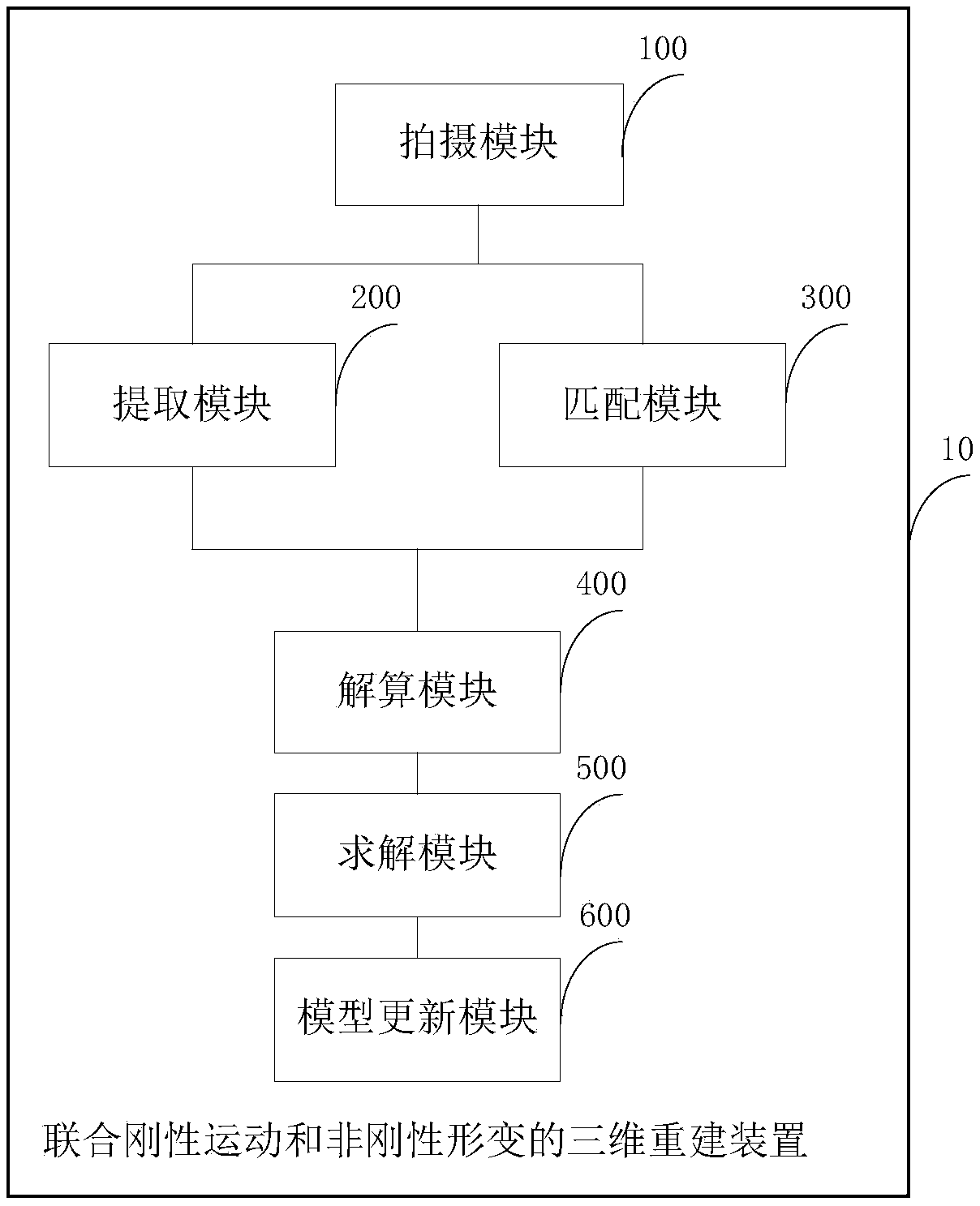
The invention discloses a three-dimensional reconstruction method and device uniting rigid motion and non-rigid deformation. The method comprises the steps that photographing based on a depth camera is performed on a target object to obtain a single depth image; three-dimensional framework extraction is performed on a depth point cloud through a three-dimensional framework extraction algorithm; amatching point pair between a three-dimensional point cloud and each reconstruction model vertex is acquired; an energy function is established according to the matching point pairs and three-dimensional framework information, non-rigid motion position transformation parameters of each vertex on a reconstruction model are solved, and object framework parameters are optimized; GPU optimal solving is performed on the energy function to obtain non-rigid deformation of each surface vertex, and the reconstruction three-dimensional model in the previous frame is deformed according to the solving result, so that the deformed model is aligned to the three-dimensional point cloud in the current frame; and the updated model in the current frame is obtained to enter iteration of the next frame. Through the method, the instantaneity, robustness and accuracy of reconstruction can be effectively improved, extensibility is high, and the method is simple and easy to implement.

Description

technical field [0001] The invention relates to the technical fields of computer vision and computer graphics, in particular to a three-dimensional reconstruction method and device combining rigid motion and non-rigid deformation. Background technique [0002] 3D reconstruction of dynamic objects is an important issue in the fields of computer graphics and computer vision. High-quality 3D models of dynamic objects, such as human bodies, animals, human faces, and human hands, have broad application prospects and important application values ​​in the fields of film and television entertainment, sports games, and virtual reality. However, the acquisition of high-quality 3D models is usually achieved by expensive laser scanners or multi-camera array systems. Although the accuracy is high, there are also some obvious disadvantages: first, the object is required to remain absolutely still during the scanning process, and the tiny Moving will lead to obvious errors in the scanning...

Claims


Application Information

Patent Timeline
IPC IPC(8): G06T17/00G06T7/521
CPCG06T17/00G06T2207/10012G06T7/521
Inventor 刘烨斌戴琼海徐枫方璐
Owner TSINGHUA UNIV
Learn More