Vapor generator with pipe diameters of communicating pipes changing in radial direction

A steam generator and generator technology, applied in steam generation, steam boilers, indirect heat exchangers, etc., can solve the problems of poor gas flow in the combustion space, low content of active ingredients, and high cost of the background technology, so as to avoid unsatisfactory heating Uniformity, fast heat transfer speed, and the effect of improving heat transfer speed

Active Publication Date: 2018-10-26
SHANDONG INST FOR FOOD & DRUG CONTROL
View PDF6 Cites 0 Cited by
  • Summary
  • Abstract
  • Description
  • Claims
  • Application Information

AI Technical Summary

Problems solved by technology

The current steam generator is also widely used in the treatment of various diseases, especially in the treatment of chronic diseases caused by aging and old damage to muscles and ligaments, such as CN2167709Y patent, but in the current prior art, such as CN2167709Y Patent, because the steam is generated directly by heating, the temperature of the generated steam will be too high, and it will cause too much moisture in the generated steam, and the drug may be deposited in the lower part because it is a particle, so the ejected steam is effective The content of ingredients is too low, and the temperature is too high, and the degree of intelligence in the existing technology is not high, and effective intelligent operation cannot be carried out
[0005] In the background technology, when the gas is used to heat the steam generator, the gas either directly heats the water tank, or generates steam through secondary heat exchange, especially directly heats the water tank, and uses the convective heat exchange inside the water tank to perform the fluid convection exchange between the upper and lower parts of the water tank. heat, but in this case, the heat fluid in the lower part needs to flow naturally to the upper part, and the heat transfer efficiency is low
[0006] In the background technology, the inventor has developed such as figure 1 The above-mentioned structure has greatly improved the heat energy absorption, but because the heat pipe evaporation end extends to the combustion space, the gas flow in the combustion space is not good, and the combustion cannot be fully carried out, and the cost of the background technology is relatively high, so this The application has carried out further improvement on the basis of the background technology

Method used


Image

  • Vapor generator with pipe diameters of communicating pipes changing in radial direction
  • Vapor generator with pipe diameters of communicating pipes changing in radial direction
  • Vapor generator with pipe diameters of communicating pipes changing in radial direction

Examples


Embodiment Construction

[0043] The specific embodiments of the present invention will be described in detail below in conjunction with the accompanying drawings.

[0044] In this article, if there is no special explanation, when it comes to formulas, " / " means division, and "×" and "*" mean multiplication.

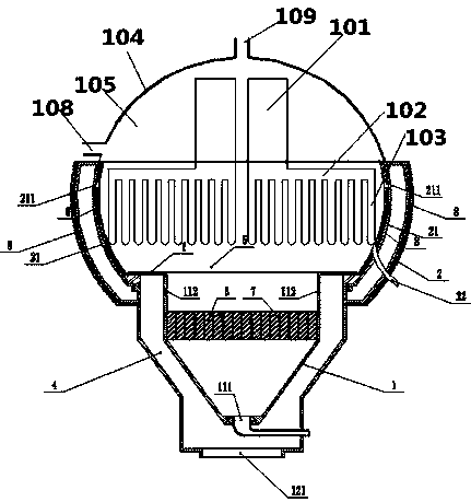
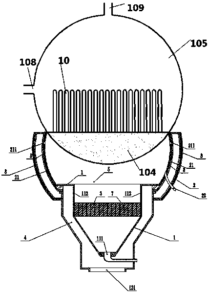
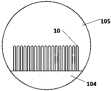
[0045] like Figure 2-6Disclosed is a gas-fired steam generator utilizing heat pipes, the steam generator includes a burner and a water tank 105, the water tank 105 includes a water inlet 108 and a steam outlet 109, and the combustion of the burner will heat the water in the water tank 105, Described steam generator also comprises the heat pipe that is arranged in water tank 105, as figure 2 As shown, the heat pipe is arranged inside the water tank 105, the heat pipe includes a header 104 and a heat dissipation end 10, the header 104 is arranged at the bottom of the water tank 105, the heat dissipation end 103 communicates with the header 104, and the heat dissipation The ends 10 extend upward...


PUM


Abstract

The invention provides a vapor generator which comprises a combustor and a water tank. The water tank comprises a water inlet and a vapor outlet and is arranged on the upper portion of the combustor.A heat pipe is arranged in the water tank and comprises a header and heat radiation ends. The header is arranged at the bottom of a vapor pocket. The heat radiation ends communicate with the header and extend upwards starting from the upper portion of the header. The multiple heat radiation ends are arranged, the communicating pipes are arranged between the adjacent heat radiation ends, and the pipe diameters of the communicating pipes are smaller and smaller in the radial direction of being outward along the center of the lower end face of the water tank. According to the vapor generator, a gas vapor generator is improved, the header and the heat radiation ends are arranged at the bottom of the water tank, the pipe diameters of the heat pipe change, and therefore the pressure of the overall heat pipe keeps basically equal, the overall heat exchange efficiency is improved, materials are saved, partial damage caused by non-uniform temperature is avoided, and the service life of the heatradiation ends is prolonged.

Description

technical field [0001] The invention relates to a steam generator technology, in particular to a steam generator of a heat pipe with a new structure. Background technique [0002] Heat pipe technology is a heat transfer element called "heat pipe" invented by George Grover of Los Alamos National Laboratory in the United States in 1963. It makes full use of the principle of heat conduction and phase change medium. The rapid heat transfer properties of the heat pipe quickly transfer the heat of the heating object to the heat source, and its thermal conductivity exceeds that of any known metal. [0003] Heat pipe technology was widely used in aerospace, military and other industries before. Since it was introduced into the radiator manufacturing industry, people have changed the traditional radiator design ideas and got rid of the single heat dissipation mode that only relies on high air volume motors to obtain better heat dissipation. The use of heat pipe technology enables th...

Claims


Application Information

Patent Timeline
Patent Type & Authority Applications(China)
IPC IPC(8): F22B31/08F28D15/02A61H33/06
CPCA61H33/065A61H2033/068A61H2201/105F22B31/08F28D15/02
Inventor 谢强胜张中湖于海英李启艳高天阳钟兵黄雪涛
Owner SHANDONG INST FOR FOOD & DRUG CONTROL
Why Eureka
Try Eureka