Hydraulic shearing mechanism auxiliary shear blade with supporting erecting device

A technology of shear mechanism and scissor blade, which is applied in the field of remote control maintenance, can solve the problems that the design of the secondary shear blade is not reasonable enough, the blade cannot provide certain support for the pipe being cut, and it cannot be very good.

Inactive Publication Date: 2018-10-26
DONGGUAN UNIV OF TECH
View PDF0 Cites 0 Cited by
  • Summary
  • Abstract
  • Description
  • Claims
  • Application Information

AI Technical Summary

Problems solved by technology

[0005] The purpose of the present invention is to solve the technical problem that the cutting edge cannot provide certain support for the pipe being cut well, and the cutting can not be completed vertically well, and provides a hydraulic shearing machine with a supporting device. The auxiliary scissor blade of the mechanism. By setting the movable shear blade and the auxiliary blade force adjustment bolt in the device, the blade can provide a certain support for the pipeline when cutting the pipeline, and can achieve vertical completion. The effect of shearing has a wide range of practicability, so as to solve the problem that the design of the existing secondary shearing edge proposed in the above-mentioned background technology is not reasonable enough, and it cannot make the blade provide certain support for the shearing pipeline well, and it cannot be very ok done the shearing question on a vertical scale

Method used


Image

  • Hydraulic shearing mechanism auxiliary shear blade with supporting erecting device
  • Hydraulic shearing mechanism auxiliary shear blade with supporting erecting device
  • Hydraulic shearing mechanism auxiliary shear blade with supporting erecting device

Examples


Embodiment Construction

[0027] The following will clearly and completely describe the technical solutions in the embodiments of the present invention with reference to the accompanying drawings in the embodiments of the present invention. Obviously, the described embodiments are only some, not all, embodiments of the present invention. Based on the embodiments of the present invention, all other embodiments obtained by persons of ordinary skill in the art without making creative efforts belong to the protection scope of the present invention.

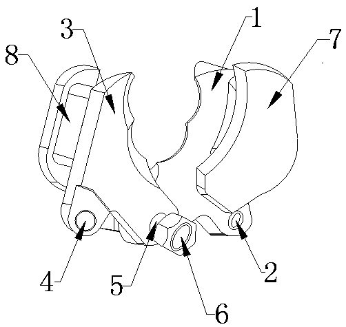
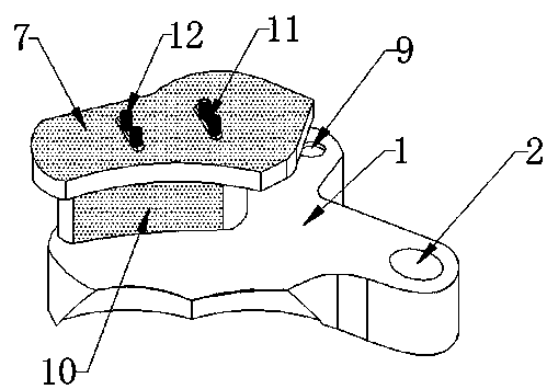
[0028] The right scissor blade used in the present invention-1, the connection hole-2, the left scissor blade-3, the connection movable hole-4, the embedded hole-5, the movable bolt-6, the movable shear blade-7, the auxiliary blade- 8. The movable hole-9, the connecting block-10, the force adjusting bolt-11 and the movable bar groove-12 can all be purchased from the market or obtained by private order.

[0029] 1. See Figure 1~3 , in an embodiment of the pre...


PUM


Abstract

The invention provides a hydraulic shearing mechanism auxiliary shear blade with a supporting erecting device. The auxiliary shear blade comprises a right-side shear blade body, a left-side shear blade body and a movable bolt, a connecting hole is fixedly formed in the right side of the bottom end of the right-side shear blade body in a penetrating mode, a connecting movable hole is fixedly formedin the left side of the bottom of the left-side shear blade body in a penetrating mode, an embedding hole is fixedly formed in the right side of the bottom of the left-side shear blade body in a penetrating mode, the front end of the right-side shear blade body is fixedly connected with a movable shear blade body, the back surface of the left-side shear blade body is fixedly connected with an auxiliary blade body, the movable shear blade body is made of no. forty-five steel, moreover, the movable shear blade body is fixedly connected with the right-side shear blade body through a connecting block, the edge of the front end of the movable shear blade body is movably connected with the edge of the auxiliary blade body. When a user uses the auxiliary shear blade body and the right-side shearblade body and the left-side shear blade body move, the movable shear blade body and the right-side shear blade body move together, the production and the use of the hydraulic shearing mechanism auxiliary shear blade with the supporting erecting device are convenient, and the auxiliary shear blade has a good development prospect.

Description

technical field [0001] The invention relates to the technical field of remote control maintenance, in particular to an auxiliary scissor blade of a hydraulic shearing mechanism with a centralizing device. Background technique [0002] Nuclear physics devices have the characteristics of high-speed operation, continuous operation, complex internal structure, large area, and heavy load, especially the equipment and operating environment can produce radiation effects. Since radiation shortens the service life of critical components, the possibility of abnormal components is greatly increased. If the main equipment or components in the device are abnormal, it may lead to two consequences: one is to affect the accuracy of the experimental results, and the other is to cause the equipment to fail to work normally. In severe cases, nuclear pollution and other major accidents that endanger the environment may occur , to bring greater obstacles to the rapid development of society. Th...

Claims


Application Information

Patent Timeline
Patent Type & Authority Applications(China)
IPC IPC(8): B23D35/00B23D21/00
CPCB23D35/001B23D21/00B23D35/002
Inventor 陈海彬刘宇
Owner DONGGUAN UNIV OF TECH
Why Eureka
Try Eureka