Power supply device, apparatus, and control method
A power supply device and equipment technology, applied in battery/fuel cell control devices, control/regulation systems, output power conversion devices, etc., can solve problems such as unoptimized switching, maintain control stability, simplify changes, and simplify actions. The effect of changing the mode
- Summary
- Abstract
- Description
- Claims
- Application Information
AI Technical Summary
Problems solved by technology
Method used
Image
Examples
no. 1 example
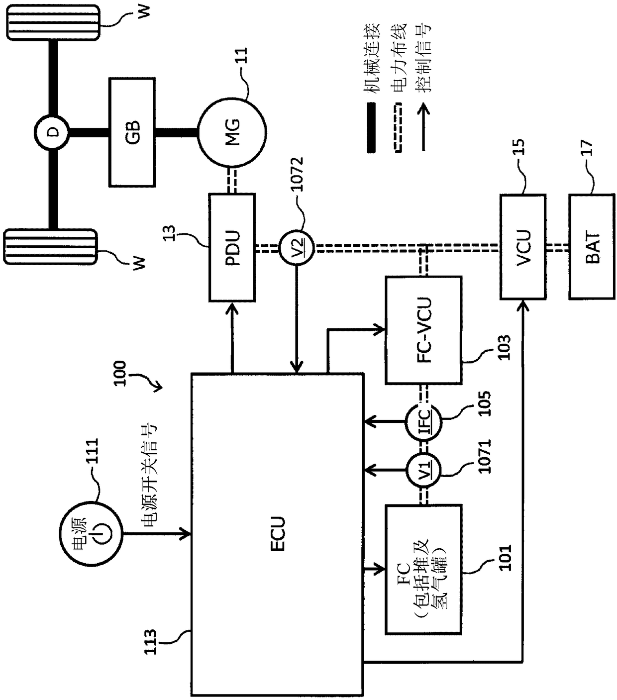
[0150] The ECU 113 of the first embodiment switches the driving modes of the phases in the FC-VCU 103 according to the on / off operation of the power switch 111 .
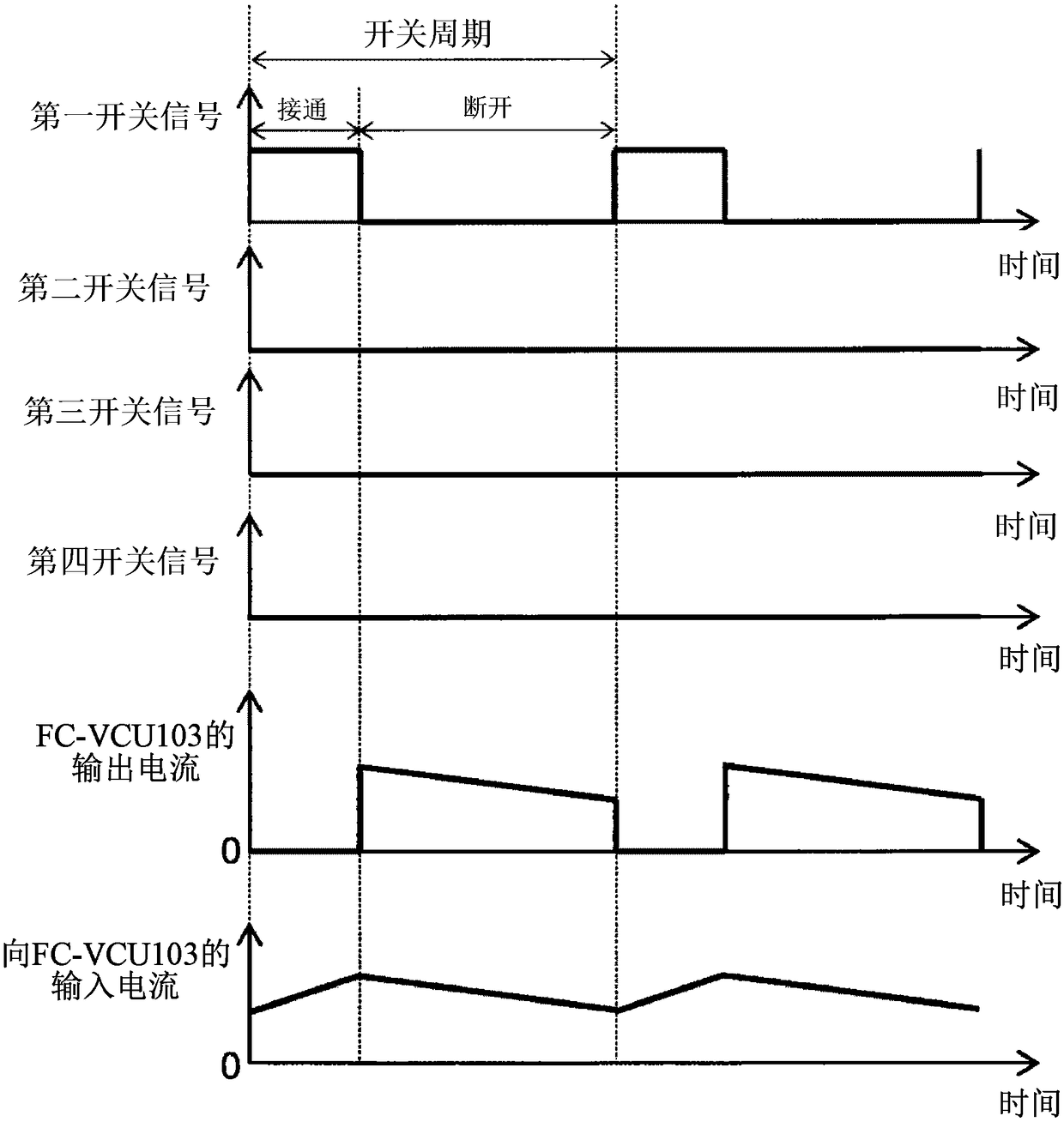
[0151] Figure 9 It is a diagram of the first embodiment showing the phases to be driven for each drive mode in the FC-VCU 103 in accordance with the number of operating phases. The ECU 113 of the first embodiment is based on Figure 9 FC-VCU103 is controlled by any one of the four drive modes shown. For example, when driving FC-VCU103 with 1 phase in driving mode 1, ECU113 performs on / off switching control for the switching element of phase 1, and controls phase 1 with a phase difference of 180 degrees when driving with 2 phases. Each switching element of Phase 1 and Phase 2 is controlled to be ON / OFF, and when driving with 4 phases, each switching element of Phase 1 to Phase 4 is controlled to be ON / OFF with a phase difference of 90 degrees. In the case of two phases, for example, "phase 1 and phase 2" or "phas...
no. 2 example
[0160] The ECU 113 of the second embodiment is driven by a 1-phase figure 2 and Figure 6 In the illustrated magnetic coupling type FC-VCU 103 , the phase 2 or the phase 3 arranged on the inner side among the phases 1 to 4 arranged in a row on the XY plane is driven.
[0161] Figure 11 It is a diagram of the second embodiment showing the phases to be driven for each drive mode in the FC-VCU 103 in accordance with the number of operating phases. The ECU 113 of the second embodiment is based on Figure 11 FC-VCU103 is controlled by any one of the two drive modes shown. For example, when driving FC-VCU103 with 1 phase in drive mode 1, ECU113 performs on / off switching control for switching elements of phase 2, and controls phase 1 with a phase difference of 180 degrees when driving with 2 phases. Each switching element of Phase 1 and Phase 2 is controlled to be ON / OFF, and when driving with 4 phases, each switching element of Phase 1 to Phase 4 is controlled to be ON / OFF wit...
no. 3 example
[0170] The ECU 113 of the third embodiment is based on the input current IFC to the FC-VCU 103 which is also the output current of the fuel cell 101, the input voltage V1 of the FC-VCU 103 which is also the output voltage of the fuel cell 101, and the FC-VCU 103 as a target value. The output voltage V2 of the pre-created loss distribution map only determines the number of operating phases of the FC-VCU103 according to the input current IFC. In addition, in the following description, "output voltage V2 / input voltage V1" is called the boost rate of FC-VCU103.
[0171] Figure 13 is a graph showing the loss ηtotal_N in the FC-VCU 103 for each number of operating phases N with respect to the input current IFC when the input power (=IFC×V1) of the FC-VCU 103 is constant. in addition, Figure 14 It is a graph showing the loss in the FC-VCU 103 with respect to the boost rate when the input power is constant and the FC-VCU 103 is driven with a predetermined number of phases. Such a...
PUM
 Abstract
Description
Claims
Application Information
 - R&D
- Intellectual Property
- Life Sciences
- Materials
- Tech Scout
- Unparalleled Data Quality
- Higher Quality Content
- 60% Fewer Hallucinations
Browse by: Latest US Patents, China's latest patents, Technical Efficacy Thesaurus, Application Domain, Technology Topic, Popular Technical Reports.
© 2025 PatSnap. All rights reserved.Legal|Privacy policy|Modern Slavery Act Transparency Statement|Sitemap|About US| Contact US: help@patsnap.com


