Valve train and engine assembly

A valve train, engine technology, applied in engine components, machine/engine, engine control, etc., can solve problems such as large air exchange loss, and achieve the effect of eliminating tradeoffs and optimizing inflation motion

Pending Publication Date: 2018-10-23
BAYERISCHE MOTOREN WERKE AG
View PDF11 Cites 0 Cited by
  • Summary
  • Abstract
  • Description
  • Claims
  • Application Information

AI Technical Summary

Problems solved by technology

However, greater gas exchange losses occur here than in the known prior art valve trains with variable valve lift

Method used


Image

  • Valve train and engine assembly
  • Valve train and engine assembly
  • Valve train and engine assembly

Examples


Embodiment Construction

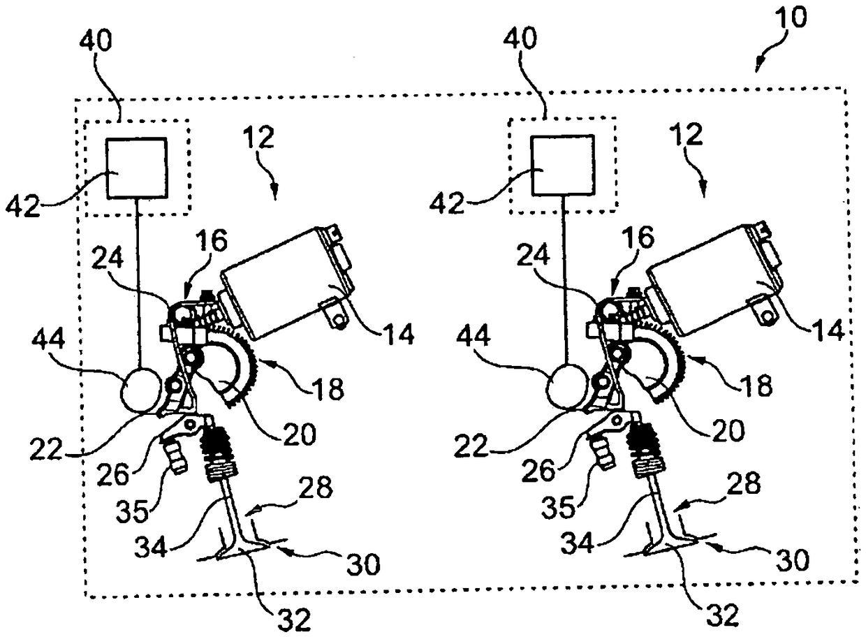
[0044] figure 1 A valve train 10 for a motor vehicle engine and its valves is shown. In the embodiment shown, the valve train 10 comprises two driven actuator units 12 which are not coupled to one another.

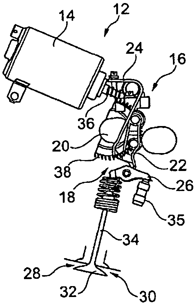
[0045] Each actuator unit 12 has its own electromechanical servo drive 14 and an actuator 16 comprising an adjusting shaft 18 with an adjusting cam 20 mounted thereon and an intermediate lever 22 acting on the adjusting cam 20 from the outside. . The intermediate lever 22 is prestressed onto the camshaft 44 via the return spring 24 . The intermediate lever 22 is driven by a camshaft 44 .

[0046] The adjusting shaft 18 can be an eccentric shaft, so that the at least one adjusting cam 20 is an eccentric wheel.

[0047] The intermediate lever 22 also drives the tug lever 26 , which operates the valve 28 with the valve seat 30 and the valve member 32 . The valve element 32 is coupled to the roller rod 26 via a valve lifter 34 . The valve element 32 and the valve lifter...


PUM


Abstract

The invention relates to a valve train (10) for an engine of a motor vehicle, comprising at least two valves (28), which are designed as intake valves or as exhaust valves, and at least two motorizedactuating units (12), which are independent of each other. A first actuating unit (12) of the at least two actuating units (12) is associated with a first valve (28) of the at least two valves (28), and a second actuating unit (12) of the at least two actuating units (12) is associated with a second valve (28) of the at least two valves (28). The actuating units (12) set the maximum valve lifts ofthe valves (28) independently of each other. The invention further relates to an engine assembly.

Description

technical field [0001] The invention relates to a valve train and an engine assembly for a motor vehicle engine. Background technique [0002] Valve trains for motor vehicle engines are known from the prior art, in which the maximum valve lift of at least two valves of a cylinder is adjusted via a common driven actuator unit comprising a At least one adjusting shaft for adjusting the cam. The valves are typically intake valves. The valve lift curves of the two valves have a fixed relative coupling due to the common actuating unit, so that a valve lift value of the first valve is associated with a predefined valve lift value of the second valve. Due to this fixed coupling, the necessary compromises must be made for all operating points. [0003] It is known from the prior art to optimize the valve control so that an improved charging movement occurs and gas exchange losses are simultaneously reduced. This is usually achieved through coupled and mechanical valve lift varia...

Claims


Application Information

Patent Timeline
Patent Type & Authority Applications(China)
IPC IPC(8): F01L1/344F02D13/02F01L13/00
CPCF01L1/34403F02D13/0257F01L2013/0078F02D13/0207Y02T10/12F01L1/047
Inventor M·扎曼M·申克D·瓦巴尔斯
Owner BAYERISCHE MOTOREN WERKE AG
Why Eureka
Try Eureka