Switched reluctance motor
A technology of switched reluctance motor and motor stator, which is applied in the direction of AC motor control, magnetic circuit, electromechanical device, etc. It can solve the problems of large wiring span, high voltage level requirements, and high process requirements, so as to improve stability and service life. The effect of reducing the demand for withstand voltage levels and simplifying the wiring process
- Summary
- Abstract
- Description
- Claims
- Application Information
AI Technical Summary
Problems solved by technology
Method used
Image
Examples
Embodiment 1
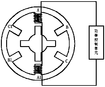
[0028] A switched reluctance motor, characterized in that: a number of salient poles are provided on the stator of the motor, wherein each salient pole is individually matched with a winding, the windings on any two salient poles are independent of each other, and each winding is connected to one or more An independent power control unit, so that the power control unit connected to each winding can individually control the power supply to the winding, wherein any salient pole can act on the motor rotor alone, and the matching of the same phase salient poles can drive the motor rotor to rotate.
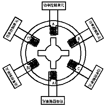
[0029] Such as figure 2 In the three-phase 6 / 4 switched reluctance motor shown, the winding on each salient pole of the stator is connected to a power control unit 4 separately, and the three-phase 6 / 4 switched reluctance motor has six salient poles, so the stator is connected to There are 6 power control units 4, and each power control unit 4 independently supplies power to a winding...
Embodiment 2
[0036] A switched reluctance motor, characterized in that: a number of salient poles are provided on the stator of the motor, wherein each salient pole is individually matched with a winding, the windings on any two salient poles are independent of each other, and each winding is connected to one or more An independent power control unit, so that the power control unit connected to each winding can individually control the power supply to the winding, wherein any salient pole can act on the motor rotor alone, and the matching of the same phase salient poles can drive the motor rotor to rotate.
[0037] The windings on the matched salient poles of the same phase are independent and not connected to each other; the power control units 4 connected to the windings on the salient poles of the same phase are independent of each other.
[0038] In the present invention, the same-phase windings are independent and disconnected from each other, which can simplify the wiring process, reduc...
Embodiment 3
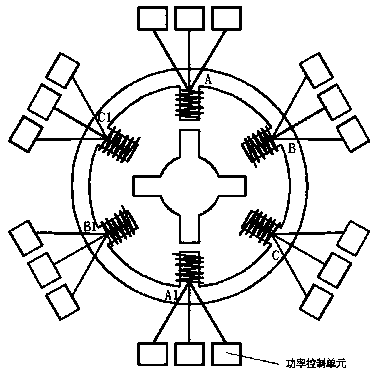
[0040] A switched reluctance motor, characterized in that: a number of salient poles are provided on the stator of the motor, wherein each salient pole is individually matched with a winding, the windings on any two salient poles are independent of each other, and each winding is connected to one or more An independent power control unit, so that the power control unit connected to each winding can individually control the power supply to the winding, in which any salient pole can act on the motor rotor alone, and the matching of the salient poles in the same phase can drive the motor rotor to rotate; non-in-phase The drive windings on any two salient poles of any two are independent and not connected to each other; the power control units 4 connected to the windings on non-salient poles of the same phase are independent of each other.
[0041] In this embodiment, the windings of different phases are independent and disconnected, so that when a motor is working, the different p...
PUM
 Abstract
Description
Claims
Application Information
 - R&D Engineer
- R&D Manager
- IP Professional
- Industry Leading Data Capabilities
- Powerful AI technology
- Patent DNA Extraction
Browse by: Latest US Patents, China's latest patents, Technical Efficacy Thesaurus, Application Domain, Technology Topic, Popular Technical Reports.
© 2024 PatSnap. All rights reserved.Legal|Privacy policy|Modern Slavery Act Transparency Statement|Sitemap|About US| Contact US: help@patsnap.com


