
Ejection-drive closed-loop backflow pulse-type transonic wind tunnel flow field control method

A closed-loop control and control method technology, applied in the direction of electric fluid pressure control, fluid pressure control, non-electric variable control, etc.

Active Publication Date: 2018-10-23
INST OF HIGH SPEED AERODYNAMICS OF CHINA AERODYNAMICS RES & DEV CENT
View PDF5 Cites 18 Cited by
  • Summary
  • Abstract
  • Description
  • Claims
  • Application Information

AI Technical Summary

Problems solved by technology

[0005] The purpose of the present invention is to provide a temporary sub-transonic wind tunnel with closed-loop backflow driven by ejection for the problem that the closed-loop backflow temporary sub-transonic wind tunnel cannot realize the operation of different M numbers under the same total pressure Flow field control method

Method used


Image

  • Ejection-drive closed-loop backflow pulse-type transonic wind tunnel flow field control method
  • Ejection-drive closed-loop backflow pulse-type transonic wind tunnel flow field control method
  • Ejection-drive closed-loop backflow pulse-type transonic wind tunnel flow field control method

Examples


Embodiment Construction

[0070] The present invention will be further described in detail below in conjunction with the accompanying drawings, so that those skilled in the art can implement it with reference to the description.

[0071] It should be understood that terms such as "having", "comprising" and "including" as used herein do not entail the presence or addition of one or more other elements or combinations thereof.

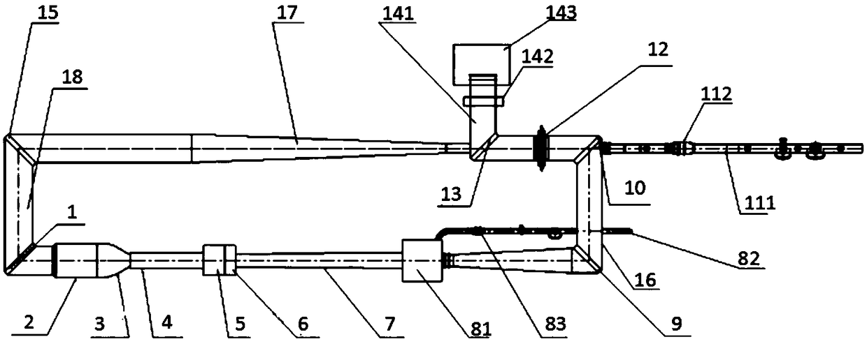
[0072] figure 1 It is a schematic diagram of the aerodynamic profile of the wind tunnel related to the present invention, such as figure 1 As shown, the wind tunnel includes: return pipeline; fourth corner section 1, stable section 2, contraction section 3, nozzle section 4, test section 5, bracket section 6, diffuser section 7, injection 8, the first corner section 9, the second corner section 10, the auxiliary air intake system 11, the backflow regulating valve 12, the fifth corner section 13, the exhaust system 14 and the third corner section 15;

[0073] Wherein, the ejecto...


PUM


Abstract

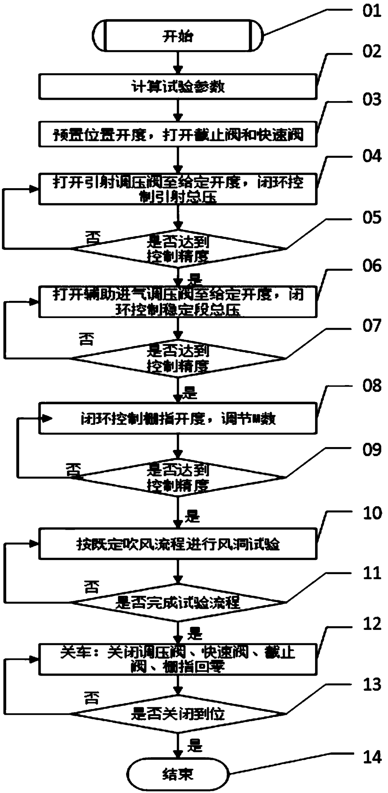
The invention discloses an ejection-drive closed-loop backflow pulse-type transonic wind tunnel flow field control method. An ejector passing by a diffusion segment is taken as the main drive of a wind tunnel flow field, and stable subsonic and transonic flow fields are built under the cooperation of a backflow regulating valve, an auxiliary air incoming pressure-regulating valve, an exhaust throttle and a gate finger. The method achieves the precise control of the total pressure of a stable segment under the joint action of an ejector pressure regulating valve and the auxiliary air incoming pressure-regulating valve, and can achieve the precise control of any given value M under the same total pressure in a subsonic and transonic speed range under the cooperation with a gate finger systembased on the above. According to the invention, a conventional blow-down pulse-type wind tunnel is upgraded to a sucking-type pulse-type wind tunnel, thereby facilitating the reduction of the impacton the dynamic flow field indexes of a wind tunnel from the high-pressure air flow pulsation of an incoming flow and the noise, facilitating the improvement of the dynamic quality of the flow field ofthe wind tunnel, and facilitating the improvement of the pulsation pressure, vibration and dynamic derivative test data.

Description

technical field [0001] The invention relates to the field of flow field control of a temporary subtransonic wind tunnel, in particular to a method for controlling the flow field of a semi-return temporary subtransonic wind tunnel for an ejector system and an exhaust throttling system. Background technique [0002] A wind tunnel is a pipeline-shaped ground test simulation device that can artificially generate and control airflow to simulate the flow of air around an aircraft or object, measure the effect of airflow on an object, and observe physical phenomena. According to the simulation speed, wind tunnels are divided into low-speed wind tunnels (M≤0.4), high-speed wind tunnels (0.4<M≤4.5) and hypersonic wind tunnels (M≥5.0). In the high-speed wind tunnel, it is divided into sub-transonic wind tunnel (M=0.4~1.4) and supersonic wind tunnel (M=1.5~4.5). The wind tunnel simulates the corresponding M number by controlling the pressure ratio of the airflow in the wind tunnel ...

Claims


Application Information

Patent Timeline
IPC IPC(8): G05D16/20
CPCG05D16/2013
Inventor 熊波秦建华徐来武阎成陈海峰丁寿和蒋明华顾海涛庞旭东杨轶成祖孝勇高川
Owner INST OF HIGH SPEED AERODYNAMICS OF CHINA AERODYNAMICS RES & DEV CENT
Learn More