Flexible membrane mechanism, flow path member, liquid ejecting apparatus, and control method
A control method and membrane technology, applied to control valves, valve devices, engine components, etc., can solve the problems of large-scale and high cost
- Summary
- Abstract
- Description
- Claims
- Application Information
AI Technical Summary
Problems solved by technology
Method used
Image
Examples
Embodiment approach 1
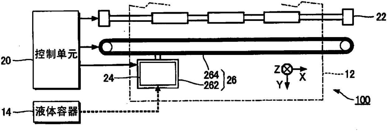
[0054] figure 1 It is a diagram showing the configuration of the liquid ejecting device according to Embodiment 1 of the present invention. The liquid ejecting device 100 of the present embodiment is an inkjet recording device that ejects liquid ink onto a medium 12 . As the medium 12, paper, a resin film, cloth, etc. are mentioned, for example.
[0055] In the liquid ejecting device 100, a liquid container 14 storing ink is fixed. Examples of the liquid container 14 include an ink cartridge detachable from the liquid ejecting device 100 , a pouch-shaped ink bag made of a flexible film, an ink tank capable of replenishing ink, and the like. In addition, although not particularly illustrated, a plurality of types of inks of different colors or types may be stored in the liquid container 14 .
[0056] Furthermore, the liquid ejecting device 100 includes a control unit 20 as a control unit, a transport mechanism 22 , and a liquid ejecting head 24 .
[0057] Although not parti...
Embodiment approach 2
[0143] Figure 17 It is a cross-sectional view of main parts of the flow channel unit according to Embodiment 2 of the present invention, and is represented by Figure 5 The sectional view based on the B-B' line. In addition, the same code|symbol is attached|subjected to the same member as the above-mentioned embodiment, and overlapping description is abbreviate|omitted.
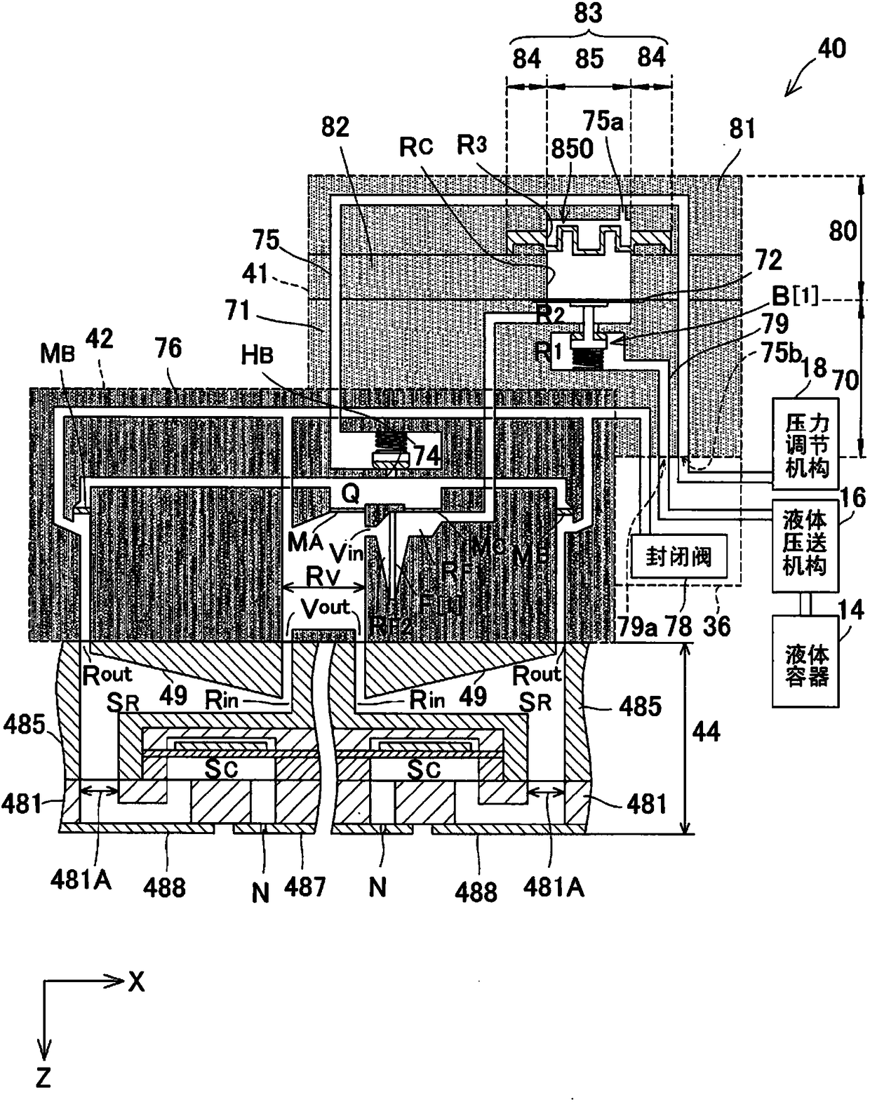
[0144] In this embodiment, in the central portion of the flexible film 83 in the Y direction, the Figure 6 Likewise, a second region 871 is formed.
[0145] In contrast to this, as Figure 17 As shown, at both ends of the flexible film 83 in the Y direction, by making the thickness t1 of the first connecting portion 853 thicker than Figure 6 The thickness t2 of the central portion is shown, thereby forming a first region 870 . That is, in the present embodiment, the protruding portion 850 is provided so as to have the same protruding amount across the circumferential direction of the contact portion 8...
Embodiment approach 3
[0150] Figure 18 It is a cross-sectional view of main parts of the flow channel unit according to Embodiment 3 of the present invention, and is represented by Figure 5 The C-C' line is the reference cross-sectional view. In addition, the same code|symbol is attached|subjected to the same member as the above-mentioned embodiment, and overlapping description is abbreviate|omitted.
[0151] Such as Figure 18 As shown, the spacer 82 is provided with a restricting portion 822 protruding into the penetrating portion 821 , that is, into the control chamber RC. The restriction|limiting part 822 is provided so that it may protrude toward the center part in the Y direction from both end parts in the Y direction of control chamber RC. That is, the restricting portion 822 is provided so as to protrude toward the center portion in the Y direction from both wall surfaces of the penetration portion 821 in the Y direction, and is not formed on the wall surface of the penetration portion...
PUM
 Abstract
Description
Claims
Application Information
 - R&D
- Intellectual Property
- Life Sciences
- Materials
- Tech Scout
- Unparalleled Data Quality
- Higher Quality Content
- 60% Fewer Hallucinations
Browse by: Latest US Patents, China's latest patents, Technical Efficacy Thesaurus, Application Domain, Technology Topic, Popular Technical Reports.
© 2025 PatSnap. All rights reserved.Legal|Privacy policy|Modern Slavery Act Transparency Statement|Sitemap|About US| Contact US: help@patsnap.com


