
Sub-pixel-level real-time dynamic tumor image localization and matching method

A real-time dynamic, matching method technology, applied in the field of medical image processing, can solve the problems of high time and space complexity of algorithms, long image matching time, increase the pressure of doctors to diagnose and treat patients, and other problems, so as to avoid the size of tumor images. limitations, avoid data training and high time complexity, reduce pain and treatment costs

Active Publication Date: 2018-10-19
QILU UNIV OF TECH
View PDF7 Cites 5 Cited by
  • Summary
  • Abstract
  • Description
  • Claims
  • Application Information

AI Technical Summary

Problems solved by technology

The disadvantages of this method are as follows: 1) A large amount of tumor tissue data is required for the neural network to learn, and the learning process takes a lot of time; 2) If the data samples are not enough, the recognition results will also be unsatisfactory during the recognition process, etc. Difficulty; 3) During the learning process, a certain amount of storage space is required for data storage; 4) Due to individual differences in tumors, it also plays a certain role in hindering the learning of neural networks; 5) The accuracy of its recognition and matching results Integer pixel level
[0004] For the traditional sliding window method and eigenvalue method, although the learning process of the neural network can be avoided, if it is directly applied to cancer identification and matching, its disadvantages are as follows: 1) The matching result of the sliding window method is relatively accurate, but the algorithm time High complexity and space complexity, resulting in long image matching time
2) For some auxiliary diagnosis and treatment equipment, if the accuracy can only be matched to an integer pixel, it will lead to poor auxiliary judgment results
The above problems will greatly reduce the efficiency of cancer diagnosis and treatment; and increase the pressure on doctors and the suffering of patients

Method used


Image

  • Sub-pixel-level real-time dynamic tumor image localization and matching method
  • Sub-pixel-level real-time dynamic tumor image localization and matching method
  • Sub-pixel-level real-time dynamic tumor image localization and matching method

Examples


Embodiment

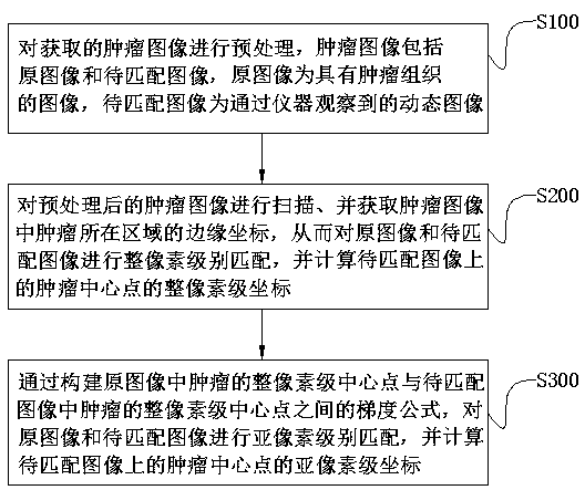
[0056] as attached figure 1 As shown, the positioning and matching method of the sub-pixel level real-time dynamic tumor image of the present invention comprises the following steps:

[0057] S100. Preprocessing the acquired tumor image, the tumor image includes an original image and an image to be matched, the original image is an image with tumor tissue, and the image to be matched is a dynamic image observed by an instrument;

[0058] S200. Scan the preprocessed tumor image, and obtain the edge coordinates of the tumor area in the tumor image, perform integer-pixel matching on the original image and the image to be matched, and calculate the integer pixel of the tumor center point on the image to be matched class coordinates;

[0059] S300. By constructing a gradient formula between the integer-pixel-level center point of the tumor in the original image and the integer-pixel-level center point of the tumor in the image to be matched, perform sub-pixel level matching on the...


PUM


Abstract

The invention discloses a sub-pixel-level real-time dynamic tumor image localization and matching method, belongs to the field of medical image processing, and aims to quickly and accurately match andlocate the tumor tissue in the real-time dynamic image. The method comprises the following steps: pre-processing acquired tumor images, wherein the tumor images include an original image and a imageto be matched; scanning the pre-processed tumor images, and acquiring the edge coordinates of the region where a tumor is located in the tumor images, thereby performing integer pixel level matching of the original image and the image to be matched, and calculating the integer pixel level coordinates of a tumor center point on the image to be matched; and using a gradient algorithm to perform sub-pixel-level matching on the original image and the image to be matched, and calculating the sub-pixel-level coordinates of the tumor center point on the image to be matched. This method enables precise matching and localization of the tumor location.

Description

technical field [0001] The invention relates to the field of medical image processing, in particular to a sub-pixel level real-time dynamic tumor image positioning and matching method. Background technique [0002] With the help of computer vision technology, the obtained tumor images are analyzed, identified and matched, which can quickly and accurately detect tumors and help medical experts in diagnosis and treatment. At present, the three main methods for tumor identification and matching are neural network learning method, traditional sliding window method, and eigenvalue method. [0003] The current common tumor recognition technology is to use neural networks to learn the appearance of tumor tissue in advance, and then apply it to tumor recognition. The disadvantages of this method are as follows: 1) A large amount of tumor tissue data is required for the neural network to learn, and the learning process takes a lot of time; 2) If the data samples are not enough, the ...

Claims


Application Information

Patent Timeline
Patent Type & Authority Applications(China)
IPC IPC(8): G06T7/00G06T7/13G16H30/20G16H50/20
CPCG06T7/0012G06T2207/30096G06T7/13G16H30/20G16H50/20
Inventor 王春鹏夏之秋马宾
Owner QILU UNIV OF TECH
Learn More