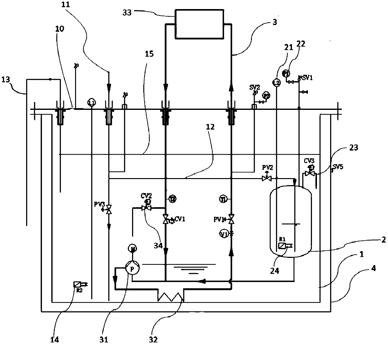
Cooling cycle system with pressure control device
A circulation system and closed circulation technology, which is applied in the field of pressure control system and cooling circulation system, can solve the problem of no pressure control design in the supercooled liquid nitrogen cooling system, and achieve the effect that the pressure cannot be kept stable for a long time and the pressure is stable
Inactive Publication Date: 2018-10-19
SHANGHAI INST OF APPLIED PHYSICS - CHINESE ACAD OF SCI
View PDF1 Cites 0 Cited by
- Summary
- Abstract
- Description
- Claims
- Application Information
AI Technical Summary
Problems solved by technology
[0004] There is no pressure control design specification for the subcooled liquid nitrogen cooling system of FMB Oxford in the UK
Method used
View moreImage
Smart ImageViewing Examples
Examples
Embodiment 2
[0036] Embodiment 2 is similar to Embodiment 1, except that the normal-pressure liquid nitrogen in the liquid nitrogen supply pipeline 11 is replaced by liquid nitrogen prepared by a cryogenic refrigerator, and the saturation temperature of the liquid nitrogen is less than 77.2K and greater than 63.1K.
Login to View More PUM
 Abstract
The invention relates to a cooling cycle system with a pressure control device. The cooling cycle system comprises a cold box. The cold box comprises a cold box body containing first liquid nitrogen and a closed cycle for cooling a cooling object and at least partially located inside the cold box. The cooling cycle system further comprises a pressure control container located inside the cold box and connected with the closed cycle and containing second liquid nitrogen. The pressure control container comprises a pressure sensor for characterizing the internal pressure of the pressure control container, a low-temperature regulating valve for discharging the gas second liquid nitrogen from the pressure control container and a first heater for heating the second liquid nitrogen in the pressurecontrol container. The cooling cycle system solves the pressure control problem of a supercooled liquid nitrogen cooling cycle system.
Description
technical field [0001] The pressure control system of the present invention relates to the field of mechanical manufacturing, more specifically, to a cooling cycle system with a pressure control device. Background technique [0002] The supercooled liquid nitrogen cooling circulation system is the cold source of the monochromator and cryogenic undulator in the light source device, and is the necessary condition and key equipment for its operation. The undulator is a device that generates a periodic magnetic field in a synchrotron radiation device and a free electron laser device. Compared with a vacuum internal undulator with the same parameters, the low-temperature undulator can increase the peak value of the magnetic field by about 30-50% in a low-temperature working environment, so that it can Obtain higher brightness synchrotron radiation light. The beamline transmits synchrotron radiation light to the experimental station, providing scientific experiments with high-qua...
Claims
Login to View More Application Information
Patent Timeline
 IPC IPC(8): F25D3/10F25D17/02F25D29/00
CPCF25D3/10F25D17/02F25D29/001
Inventor 王淑华李明王莉张俊峰丁先庚
Owner SHANGHAI INST OF APPLIED PHYSICS - CHINESE ACAD OF SCI
Features
- R&D
- Intellectual Property
- Life Sciences
- Materials
- Tech Scout
- Unparalleled Data Quality
- Higher Quality Content
- 60% Fewer Hallucinations
Learn More Browse by: Latest US Patents, China's latest patents, Technical Efficacy Thesaurus, Application Domain, Technology Topic, Popular Technical Reports.
© 2025 PatSnap. All rights reserved.Legal|Privacy policy|Modern Slavery Act Transparency Statement|Sitemap|About US| Contact US: help@patsnap.com


