Microfluid flow on-line regulating device and detection method
A regulating device and microfluidic technology, applied in the field of microfluidics, can solve the problem that the ideal output flow of a pressure driving device is difficult to accurately calculate, and achieve the effects of online rapid detection, high measurement accuracy, and stable regulation
- Summary
- Abstract
- Description
- Claims
- Application Information
AI Technical Summary
Problems solved by technology
Method used
Image

Examples
specific Embodiment approach 1
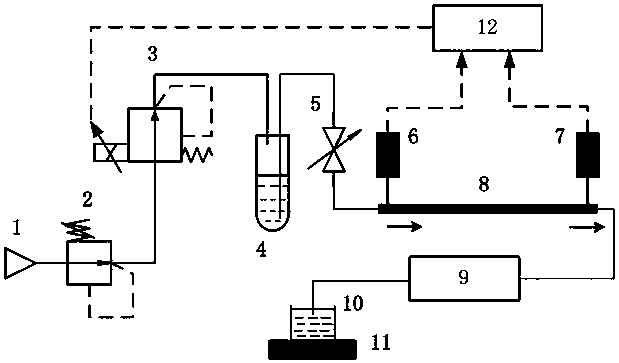
[0025] Specific implementation mode one: the following combination figure 1 and figure 2 Describe this embodiment, the microfluid flow rate online adjustment device and detection method described in this embodiment, it consists of a gas supply source 1, a pressure reducing valve 2, a proportional pressure valve 3, a first liquid container 4, a valve 5, a first pressure A sensor 6, a second pressure sensor 7, a microfluidic channel 8, a microfluidic chip 9, a second liquid container 10, a weighing instrument 11 and a microprocessor 12 are formed. in:
[0026] The gas inlet of the pressure reducing valve 2 is communicated with the compressed air outlet of the gas supply source 1, and the gas outlet of the pressure reducing valve 2 is communicated with the gas inlet of the proportional pressure valve 3;
[0027] The gas outlet of the proportional pressure valve 3 communicates with the gas inlet of the first liquid container 4, and the liquid outlet of the first liquid containe...
specific Embodiment approach 2
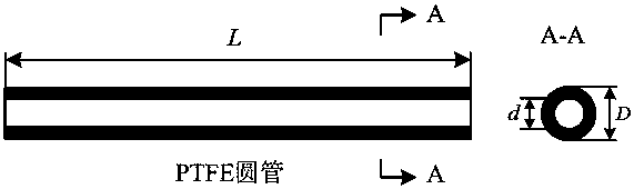
[0037] Specific implementation mode two: the following combination figure 2 This embodiment will be described, and this embodiment will further describe the first specific embodiment. In order to ensure that the microfluid flow has a linear relationship with the pressure difference at both ends of the microfluid channel 8 (the microfluid flow Q = scale factor K × differential pressure ΔP ), to realize the online accurate detection of the microfluidic flow rate, the microfluidic channel 8 adopts the PTFE round tube structure, and the length of the round tube is required L with inner diameter d The ratio is greater than 20:1, and the Reynolds number Re <1.0 of the microfluid flow is satisfied inside the circular tube, and the microfluid is in a laminar flow state.
[0038] In this embodiment, the inner diameter of the PTFE round tube d The range of change is 0.1 ~ 1.0 mm, the length of PTFE round tube L The variation range of 10.0 ~ 40.0 mm, according to the microfluidic...
specific Embodiment approach 3
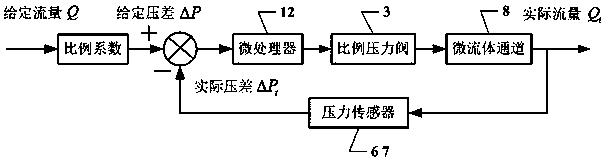
[0039] Specific implementation mode three: the following combination image 3This embodiment will be described, and this embodiment will further describe the first specific embodiment. In order to realize online stable regulation of the microfluidic flow rate, the first pressure sensor 6 and the second pressure sensor 7 respectively measure the inlet and outlet pressures of the microfluidic channel 8 to obtain the pressure difference at both ends of the microfluidic channel 8 and feed it back to the microprocessor 12, The control signal is output by the microprocessor 12 to change the gas control pressure of the proportional pressure valve 3 and adjust the microfluid flow online.
[0040] In this embodiment, the online adjustment time of the microfluid flow is less than 0.5 s, and the online adjustment accuracy of the microfluid flow reaches 0.1%.
PUM
 Abstract
Description
Claims
Application Information
 - Generate Ideas
- Intellectual Property
- Life Sciences
- Materials
- Tech Scout
- Unparalleled Data Quality
- Higher Quality Content
- 60% Fewer Hallucinations
Browse by: Latest US Patents, China's latest patents, Technical Efficacy Thesaurus, Application Domain, Technology Topic, Popular Technical Reports.
© 2025 PatSnap. All rights reserved.Legal|Privacy policy|Modern Slavery Act Transparency Statement|Sitemap|About US| Contact US: help@patsnap.com