Rotary and stable energy-dissipating type offshore lifesaving device

A life-saving device and stable technology, applied in water life-saving, wind power generation, transportation and packaging, etc., can solve the problems of life-saving cabin fluctuation, rust and block connection cover and cabin body, air bag rupture, etc., to avoid collision rupture and overturning. risk, the effect of increasing smooth performance

Inactive Publication Date: 2018-10-19
东台市海一船用设备有限公司
View PDF9 Cites 2 Cited by
  • Summary
  • Abstract
  • Description
  • Claims
  • Application Information

AI Technical Summary

Problems solved by technology

[0002] At present, when a shipwreck occurs, people generally escape by taking a small boat on a passenger ship or by wearing a life jacket. In seawater, many passengers may be killed before the arrival of the lifeguards, so it is necessary to develop a lifesaving cabin. The current lifesaving cabin has been developed, but the opening and closing structure at the upper end of the lifesaving cabin is made of It is not ideal. Generally, an airbag is installed at the bottom of the rescue cabin, but the airbag is easy to be broken after being hit, causing danger; now it is usually connected to the upper end of the cabin through a connecting cover. In addition, due to contact with seawater or even immersion, Sometimes the connection cover and the cabin will be rusted and blocked, making it difficult to open and cause safety hazards. Therefore, the opening and closing methods and safety of the existing marine lifesaving devices are not high. In addition, sometimes the sea wind is strong, and the lifesaving cabin will fluctuate or even overturning, which will lead to serious safety hazards, so it is also necessary to develop a system that can effectively prevent overturning caused by wind

Method used


Image

  • Rotary and stable energy-dissipating type offshore lifesaving device
  • Rotary and stable energy-dissipating type offshore lifesaving device
  • Rotary and stable energy-dissipating type offshore lifesaving device

Examples


Embodiment Construction

[0028] The content of the present invention will be further described in detail below in conjunction with the accompanying drawings.

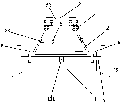
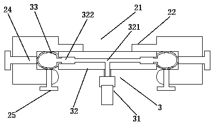
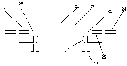
[0029] Such as figure 1 As shown, a rotating energy-consuming stable marine lifesaving device includes a floating plate 1, a rescue cabin 2, a closure assembly 3, a rotating blade 5, a positioning ring 6, and a rotating shaft 7. The floating plate 1 is installed at the bottom of the rescue cabin 2 . The upper end of the rescue cabin 2 is provided with an inlet 21 . Such as image 3 As shown, the inner side of the upper end of the rescue cabin 2 is provided with an annular installation groove 26 . Such as figure 2 with 4 As shown, the closure assembly 3 includes a connecting plate 32 , a flushing and deflation air pump 31 , and a clamping air bag 33 . The inside of the connection plate 32 is provided with a gas flow channel 321, the flushing and deflation pump 31 is installed at the bottom of the connection plate 32, the described flushin...


PUM


Abstract

The invention discloses a rotary and stable energy-dissipating type offshore lifesaving device which comprises a floating plate, a lifesaving cabin, a sealing assembly, rotating blades, a positioningring and rotating shafts. A plurality of lower semicircular grooves are formed in the upper end of the periphery of the floating plate, and a plurality of upper semicircular grooves are formed in thelower end of the positioning ring; the positioning ring fixedly covers the upper end of the periphery of the floating plate, and the upper semicircular grooves and the lower semicircular grooves are in butt joint to form circular cavities; an annular gap is formed between the edge of the lower end of the positioning ring and the edge of the upper end of the floating plate; the annular gap is communicated with the circular cavities, one ends of the rotating shafts are rotationally connected in the circular cavities, and the other ends of the rotating shafts extend out of the annular gap and then are fixed to the centers of the rotating blades. The conversion of the pushing force is realized, the overturning risk of the lifesaving cabin is effectively avoided, and the stable performance of the lifesaving cabin is improved.

Description

technical field [0001] The invention relates to a rotating energy-consuming stable marine lifesaving device. Background technique [0002] At present, when a shipwreck occurs, people generally escape by taking a small boat on a passenger ship or by wearing a life jacket. In seawater, many passengers may be killed before the arrival of the lifeguards, so it is necessary to develop a lifesaving cabin. The current lifesaving cabin has been developed, but the opening and closing structure at the upper end of the lifesaving cabin is made of It is not ideal. Generally, an airbag is installed at the bottom of the rescue cabin, but the airbag is easy to be broken after being hit, causing danger; now it is usually connected to the upper end of the cabin through a connecting cover. In addition, due to contact with seawater or even immersion, Sometimes the connection cover and the cabin will be rusted and blocked, making it difficult to open and cause safety hazards. Therefore, the op...

Claims


Application Information

Patent Timeline
Patent Type & Authority Applications(China)
IPC IPC(8): B63C9/06B63B43/10F03D1/02
CPCY02E10/72B63C9/06B63B43/10F03D1/025
Inventor 徐小龙王美兰
Owner 东台市海一船用设备有限公司
Why Eureka
Try Eureka