
Beam-forming method for NLOS scenarios in massive MIMO

A beamforming method and beamforming technology, applied in the field of communications, can solve the problems of less research on beamforming, high sensitivity to time-varying wireless channels, and high sensitivity, so as to overcome the energy dispersion of multipath beamforming. , the effect of simplifying algorithm complexity and low algorithm complexity

Active Publication Date: 2018-10-16
XIDIAN UNIV
View PDF4 Cites 9 Cited by
  • Summary
  • Abstract
  • Description
  • Claims
  • Application Information

AI Technical Summary

Problems solved by technology

[0006] (1) In the prior art, for NLOS non-line-of-sight scenarios, since the energy of each path is too dispersed, the weight value obtained by the EBB algorithm cannot be guaranteed to be optimal, so the receiving power of the desired user cannot be effectively improved;
[0007] (2) The existing technology cannot realize the beamforming of the single-user massive MIMO system in the non-line-of-sight NLOS scenario, and cannot improve the receiving power of the desired user
[0008] (3) Existing technologies are more suitable for line-of-sight LOS scenarios, and there are relatively few beamforming studies for NLOS non-line-of-sight scenarios;
[0009] (4) The ZF algorithm and MRT algorithm in the prior art need to know the channel information of each path in real time, but in the multi-path channel scenario, the channel state information of each path cannot be fully known
[0010] (5) The ZF algorithm and MRT algorithm in the prior art are highly sensitive to the time-varying wireless channel, which may affect the performance of the system in actual system applications
[0012] The difficulty in solving the above problems lies in the fact that the existing technology is relatively sensitive to the time-varying nature of the wireless channel. If the time-varying nature of the wireless channel is not considered, it will affect the performance of the system in the actual system.
In addition, due to the existence of multiple scatterers in the non-line-of-sight NLOS scene, there will be multiple paths to the receiver. On the other hand, due to path loss, the power of each path to the receiver will be relatively low. Existing The weights obtained by the beamforming algorithm in the NLOS scenario are not necessarily optimal, and there is no way to effectively increase the received power of the desired user when the power of each path is low

Method used


Image

  • Beam-forming method for NLOS scenarios in massive MIMO
  • Beam-forming method for NLOS scenarios in massive MIMO
  • Beam-forming method for NLOS scenarios in massive MIMO

Examples


Embodiment Construction

[0066] In order to make the object, technical solution and advantages of the present invention more clear, the present invention will be further described in detail below in conjunction with the examples. It should be understood that the specific embodiments described here are only used to explain the present invention, not to limit the present invention.

[0067] In the prior art, for NLOS non-line-of-sight scenarios, since the energy of each path is too dispersed, the weight value obtained by the EBB algorithm cannot be guaranteed to be optimal, so the receiving power of the desired user cannot be effectively improved;

[0068] The existing technology cannot realize beamforming of a single-user massive MIMO system in a non-line-of-sight NLOS scenario, and cannot improve the receiving power of a desired user.

[0069] The invention solves the problem that the beamforming method in the prior art has weak ability to resist channel time variation, cannot effectively improve the ...


PUM


Abstract

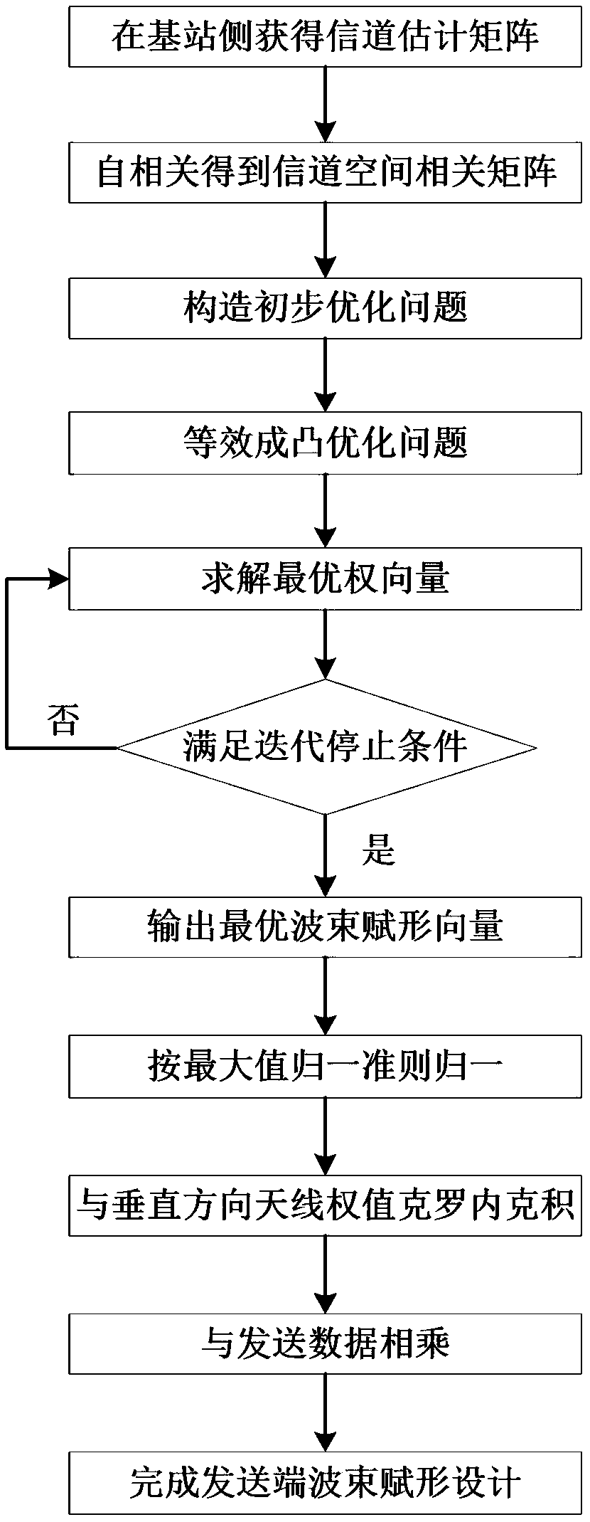
The invention belongs to the technical field of communications, and discloses a beam-forming method for NLOS scenarios in massive MIMO, comprising: obtaining a channel estimation matrix at the base station side; performing autocorrelation on the channel estimation matrix to obtain a spatial correlation matrix; constructing an optimization problem according to a maximum received signal-to-noise ratio criterion; performing equivalent minimization on the optimization problem; solving the optimal weight vector; performing maximum naturalization; performing Crohneck product with vertical antenna weight; and multiplying by transmission data. The invention has the advantages of low sensitivity to channel time-varying characteristics, strong anti-non-line-of-sight NLOS capability, low algorithm complexity and simple implementation, and finally improves the receiving power of the desired user. The invention solves the problems that the beam-forming method of the prior art has weak resistance tochannel time-varying, and cannot effectively improve the received power of the desired user in the case of multipath, and the algorithm has high complexity.

Description

technical field [0001] The invention belongs to the technical field of communications, and in particular relates to a beamforming method for NLOS scenarios in massive MIMO. Background technique [0002] At present, the existing technologies commonly used in the industry are as follows: [0003] After decades of rapid development, the popularity of small mobile communication devices, the performance changes related to the Internet of Things, and the demand for data services such as multimedia have shown explosive growth, and the traffic of mobile wireless communication has increased significantly. Facing such needs, long-term evolution ( LTE) and LTE-A will not be able to meet in the near future, so the fifth generation (5G) mobile communication system is expected to be realized in 2020, through technological evolution and innovation, 5G can fully utilize a series of emerging technologies to meet In the future, a wide range of data services and connections will be developed...

Claims


Application Information

Patent Timeline
Patent Type & Authority Applications(China)
IPC IPC(8): H04B7/0413H04B7/06H04L25/02
CPCH04B7/0413H04B7/0617H04L25/0242Y02D30/70
Inventor 任光亮张耀庭张会宁王奇伟
Owner XIDIAN UNIV
Learn More