
Gradual locking type LED ceiling down lamp

A ceiling and locking technology, applied in the direction of light source fixing, fixed lighting devices, lighting and heating equipment, etc., can solve problems such as bumping users, unstable installation, and unmatched size of downlights

Inactive Publication Date: 2018-10-16
芜湖七创工业设计有限公司
View PDF0 Cites 5 Cited by
  • Summary
  • Abstract
  • Description
  • Claims
  • Application Information

AI Technical Summary

Problems solved by technology

[0002] At present, the common installation method of ceiling downlights on the market is mainly to use the spring clips on both sides of the downlight housing to install on the ceiling. However, due to the inconsistent thickness of the ceilings of different buildings, it is necessary to select the appropriate one according to the size of the ceiling in advance when installing the downlight. Downlights are very troublesome. In addition, if errors occur during the construction of the ceiling and the size of the downlights cannot match, there will be a phenomenon that the downlight can be installed on the ceiling but the installation is not stable, and it will fall if it is serious bump user

Method used


Image

  • Gradual locking type LED ceiling down lamp
  • Gradual locking type LED ceiling down lamp
  • Gradual locking type LED ceiling down lamp

Examples


Embodiment Construction

[0062] The technical solutions in the embodiments of the present invention will be clearly and completely described below in conjunction with the accompanying drawings in the embodiments of the present invention

[0063] It is obvious that the described embodiments are only a part of the embodiments of the present invention, but not all of them. Based on the embodiments of the present invention, all other embodiments obtained by persons of ordinary skill in the art without making creative efforts belong to the protection scope of the present invention.

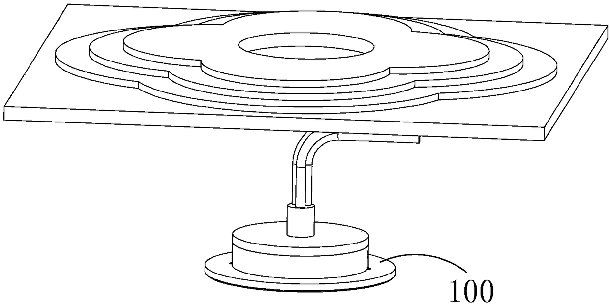
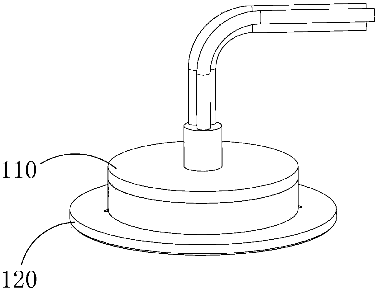
[0064] Such as Figure 1-17 As shown, the progressive locking LED ceiling downlight includes a downlight housing 100, and the downlight housing 100 is provided with a baffle 200, a suspension locking device 300, a trigger mechanism 400, and a reset mechanism 500. The said baffle The plate 200 is used to restrict the suspension locking device 300 from protruding from the downlight housing 100, and the trigger mechanism 400 is ...


PUM


Abstract

The invention provides a gradual locking type LED ceiling down lamp. The gradual locking type LED ceiling down lamp comprises a down lamp shell. Baffles, suspension locking devices, trigger mechanismsand reset mechanisms are arranged in the down lamp shell. The baffles are used for limiting the suspension locking devices from stretching out of the down lamp shell. The trigger mechanisms are usedfor controlling the baffles to limit the suspension locking devices or stop limiting the suspension locking devices. The suspension locking devices can stretch out of the down lamp shell and are usedfor enabling the down lamp to be fixedly mounted on a ceiling. The reset mechanisms are used for enabling the suspension locking devices to stop fixing the down lamp.

Description

technical field [0001] The invention relates to a ceiling downlight. Background technique [0002] At present, the common installation method of ceiling downlights on the market is mainly to use the spring clips on both sides of the downlight shell to install on the ceiling. However, due to the inconsistent thickness of the ceilings of different buildings, it is necessary to select the appropriate one according to the size of the ceiling in advance when installing the downlight. Downlights are very troublesome. In addition, if errors occur during the construction of the ceiling and the size of the downlights cannot match, there will be a phenomenon that the downlight can be installed on the ceiling but the installation is not stable, and it will even fall if it is serious Bump the user. Contents of the invention [0003] In order to solve the deficiencies of the prior art, the object of the present invention is to provide a ceiling downlight to solve the problems mentione...

Claims


Application Information

Patent Timeline
Patent Type & Authority Applications(China)
IPC IPC(8): F21S8/02F21V17/16F21V17/18F21V21/04F21Y115/10
CPCF21S8/026F21V17/162F21V17/18F21V21/048F21Y2115/10
Inventor 魏大平
Owner 芜湖七创工业设计有限公司
Learn More