
Automatic feeding method of polycrystalline silicon reduction furnace and device

An automatic feeding and reducing furnace technology, applied in chemical instruments and methods, silicon compounds, inorganic chemistry, etc., can solve the problems of complicated operation, poor repeatability, unfavorable for regular summary and adjustment, etc., to avoid manual operation and repeatability. High, the effect of preventing contamination incidents of polysilicon products

Active Publication Date: 2018-10-16
XINTE ENERGY
View PDF6 Cites 4 Cited by
  • Summary
  • Abstract
  • Description
  • Claims
  • Application Information

AI Technical Summary

Problems solved by technology

[0007] In actual production, due to the continuous increase of the surface area of ​​polysilicon rods, the concentration of materials around the silicon rods, and the influence of the thermal conditions in the reduction furnace, the amount of materials during the growth of polysilicon cannot be a fixed value, and it is necessary to manually adjust the hydrogen and The flow rate and ratio of trichlorosilane are complicated to operate, and there are high requirements for the operator's control level and operating experience
Moreover, the repeatability is poor, which is not conducive to the summary and adjustment of the law

Method used


Image

  • Automatic feeding method of polycrystalline silicon reduction furnace and device
  • Automatic feeding method of polycrystalline silicon reduction furnace and device
  • Automatic feeding method of polycrystalline silicon reduction furnace and device

Examples


Embodiment 1

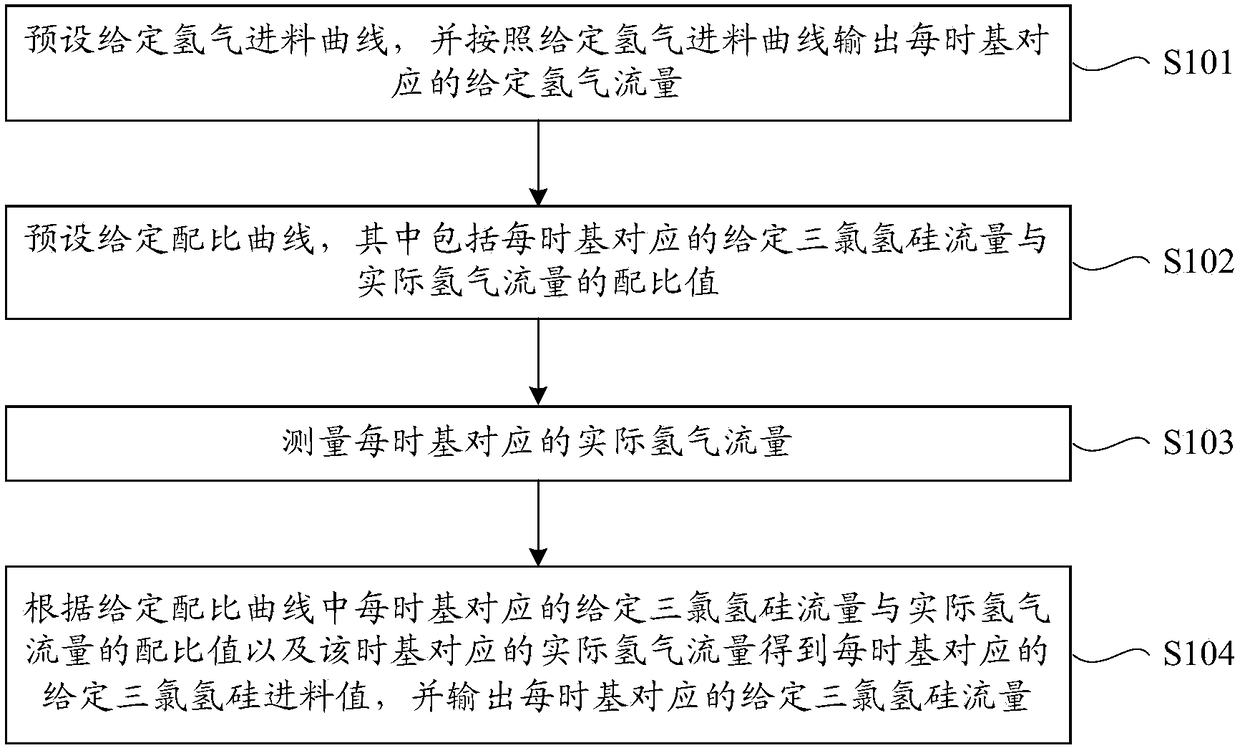
[0030] Such as figure 1 As shown, this embodiment provides an automatic feeding method for a polysilicon reduction furnace, including the following steps S101 to S104.

[0031] S101. Preset a given hydrogen feed curve, and output a given hydrogen flow corresponding to each time base according to the given hydrogen feed curve.

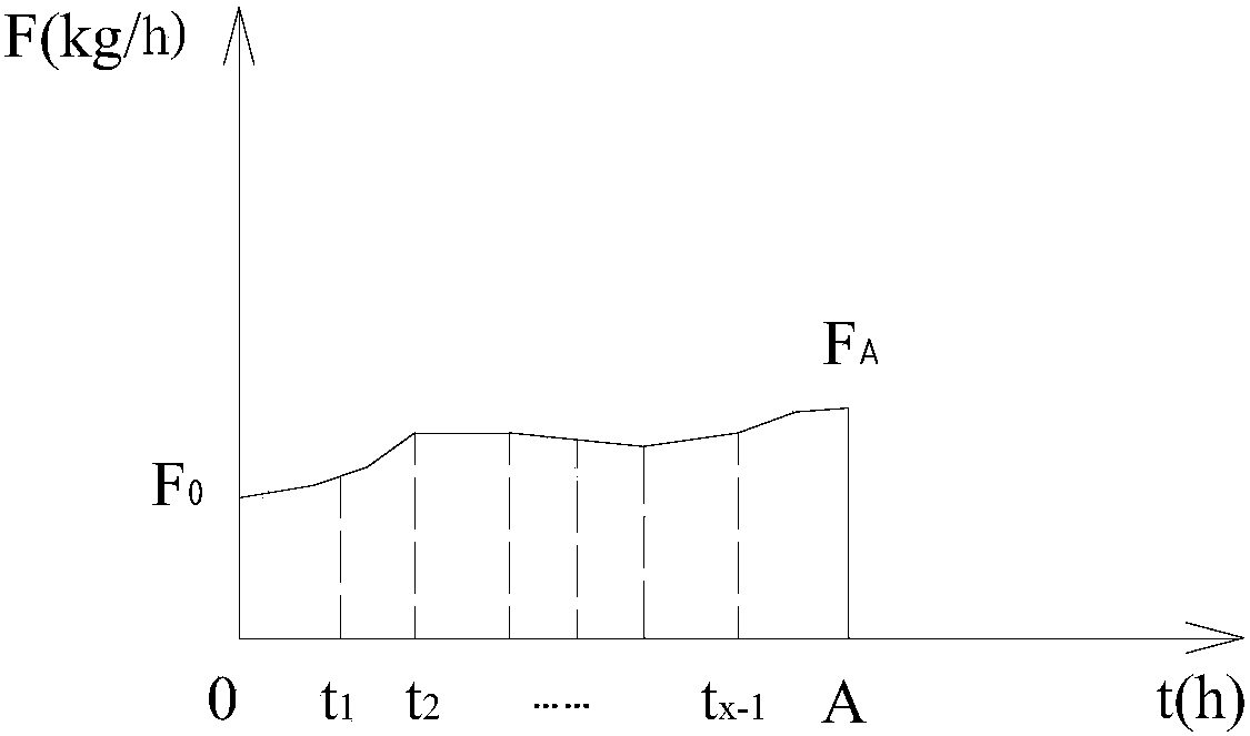
[0032] In this step, if figure 2 As shown, the given hydrogen feed curve can be represented by line segments connected end-to-end in sequence by x segments, that is, the given hydrogen feed curve can be approximately expressed as a polyline, where the time points are t 0 ,t 1 ,t 2 ,·····,t x-1 ,t x , and the corresponding given hydrogen flow values ​​in turn are F 0 ,F 1 ,F 2 ,·····,F x-1 ,F x , in the time interval formed by adjacent time points (that is, each time base), the given hydrogen flow rate changes in a straight line (increasing or decreasing), then the expression of the given hydrogen flow rate corresponding to each time base is a...

Embodiment 2

[0053] Such as Figure 4 As shown, this embodiment provides an automatic feeding device for a polysilicon reduction furnace, including a hydrogen control unit 100 , a ratio setting unit 500 , a hydrogen flow measurement unit 200 , and a trichlorosilane control unit 300 .

[0054] The hydrogen control unit 100 is used to preset a given hydrogen feed curve, and output a given hydrogen flow corresponding to each time base according to the given hydrogen feed curve.

[0055] The given hydrogen feed curve preset in the hydrogen control unit 100 can be represented by line segments connected end-to-end in turn by x segments, that is, the given hydrogen feed curve is approximately expressed as a polyline, and the time points are respectively t 0 ,t 1 ,t 2 ,·····,t x-1 ,t x , and the corresponding given hydrogen flow values ​​in turn are F 0 ,F 1 ,F 2 ,·····,F x-1 ,F x , in the time interval formed by adjacent time points (that is, each time base), the given hydrogen flow rate...


PUM


Abstract

The invention provides an automatic feeding method of a polycrystalline silicon reduction furnace. The method comprises the following steps: presetting a given hydrogen gas feeding curve, and outputting each-timebase corresponding given hydrogen gas flow rate according to the given hydrogen gas feeding curve; presetting a given proportioning curve, wherein the given proportioning curve comprises aproportioning ratio of each-timebase corresponding given trichlorosilane flow rate to actual hydrogen gas flow rate; measuring actual hydrogen gas flow rate corresponding to each timebase; and gaining a given trichlorosilane feeding value corresponding to each timebase according to the proportioning ratio of the each-timebase corresponding given trichlorosilane flow rate to the actual hydrogen gas flow rate in the given proportioning curve and the actual hydrogen gas flow rate corresponding to the corresponding timebase, and outputting given trichlorosilane flow rate corresponding to each timebase. Correspondingly, the invention provides an automatic feeding device of the polycrystalline silicon reduction furnace. According to the method and the device, the feeding of the polycrystallinesilicon reduction furnace can be automatically controlled, so that manual operation is reduced and even avoided; and the repeatability is high, so that the method and the device can adapt to differentworking conditions and parameters, and adjustment and improvement are easy.

Description

technical field [0001] The invention relates to the technical field of polysilicon production, in particular to an automatic feeding method for a polysilicon reduction furnace and an automatic feeding device for a polysilicon reduction furnace. Background technique [0002] Polysilicon is the building block material for the solar photovoltaic industry. At present, the production of polysilicon mainly adopts the modified Siemens method (that is, the reduction method of trichlorosilane). The basic principle is: use trichlorosilane (SiHCl 3 ) and hydrogen (H 2 ) in a reduction furnace according to a certain ratio for vapor deposition reaction, the reaction temperature is 1000°C-1100°C, and the polysilicon crystal particles produced are deposited and grown on the silicon core to obtain rod-shaped polysilicon. Among them, the reduction furnace is a reaction vessel for polysilicon production. [0003] The main reaction equation for polysilicon production is: [0004] SiHCl 3 ...

Claims


Application Information

Patent Timeline
Patent Type & Authority Applications(China)
IPC IPC(8): C01B33/035
CPCC01B33/035G16C20/80
Inventor 王文梁建龙张瑜龙蔡芳芳张文龙罗飞飞郑安刘方旭
Owner XINTE ENERGY
Learn More