
Microscope system used for ophthalmologic operation

A microscope system and ophthalmic surgery technology, which is applied in the field of ophthalmic surgery microscope system, can solve the problems of doctors' operation fatigue, and achieve the effect of detection and expansion of application

Active Publication Date: 2018-10-16
SHENZHEN CERTAINN TECH CO LTD
View PDF5 Cites 13 Cited by
  • Summary
  • Abstract
  • Description
  • Claims
  • Application Information

AI Technical Summary

Problems solved by technology

[0005] The purpose of the present invention is to solve the problem that the ophthalmic surgical microscope in the prior art needs the doctor to align the eyepiece for observation, which may easily cause the doctor's operation fatigue, and proposes an ophthalmic surgical microscope system

Method used


Image

  • Microscope system used for ophthalmologic operation
  • Microscope system used for ophthalmologic operation
  • Microscope system used for ophthalmologic operation

Examples


Embodiment Construction

[0042] The present invention will be described in further detail below in combination with specific embodiments and with reference to the accompanying drawings. Wherein the same reference numerals denote the same components, unless otherwise specified. It should be emphasized that the following description is only exemplary and not intended to limit the scope of the invention and its application.

[0043] In the description of the present invention, it should be noted that the terms "center", "longitudinal", "transverse", "upper", "lower", "front", "rear", "left", "right", " The orientations or positional relationships indicated by "vertical", "horizontal", "top", "bottom", "inner", "outer", etc. are based on the orientation or positional relationships shown in the drawings, and are only for the convenience of describing the present invention and simplifying Describes, but does not indicate or imply that the device or element referred to must have a specific orientation, be c...


PUM


Abstract

The invention discloses a microscope system used for an ophthalmologic operation. The system comprises a microimaging light path module, an illumination light path module, a control system and virtualreality equipment; the illumination light path module is used for providing illumination for the microscope system; an operation camera shooting module is connected with the inside of the microimaging light path module and is used for shooting an inspected eye image of a to-be-inspected object and transmitting the image to the control system; the control system receives the inspected eye image and provides the inspected eye image magnified by the microimaging light path module for virtual reality equipment. The microscope system used for the ophthalmologic operation can provide the magnifiedimage of the inspected eye for a surgeon so that the surgeon can get rid of the restriction of always looking towards an eyepiece tube, surgeons only need to wear the virtual reality equipment, and the system is beneficial for performing operations.

Description

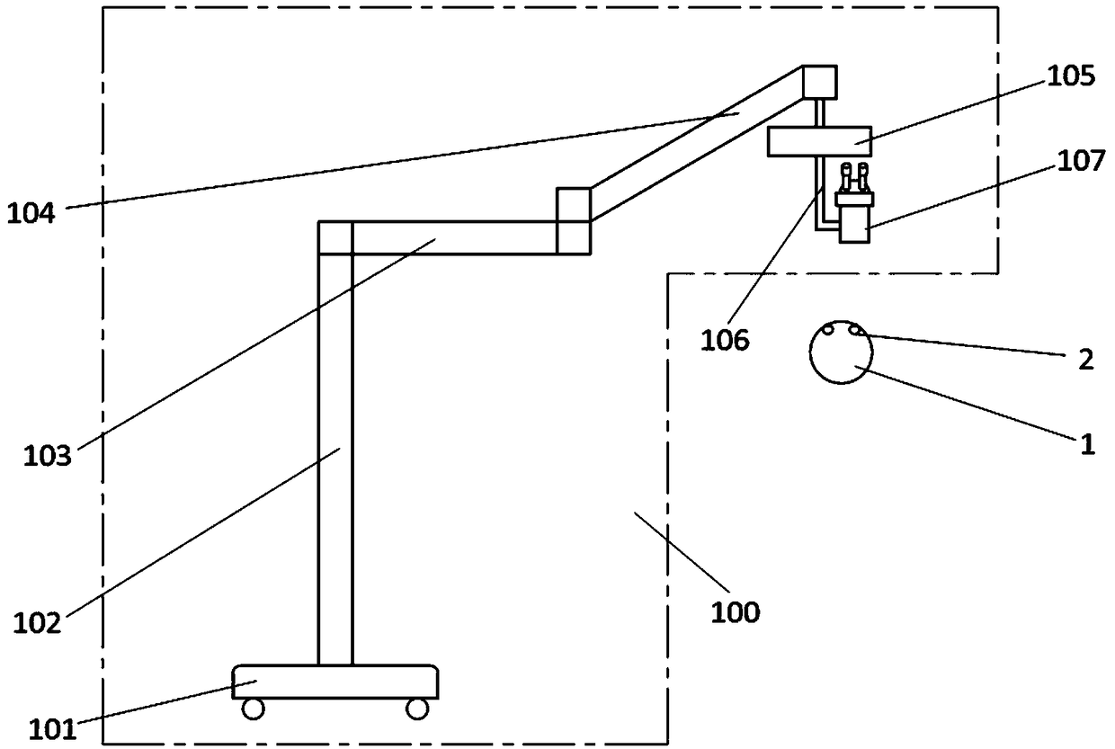
technical field [0001] The invention relates to the field of microscope equipment, in particular to an ophthalmic operating microscope system. Background technique [0002] Traditional ophthalmic operating microscope 100, its structure is generally as follows figure 1 As shown, it mainly includes a movable base 101, a column 102, a beam 103, a swing arm 104, a two-dimensional electric translation mechanism 105, a liftable connecting rod 106, and a stereoscopic surgical microscope 107. The surgical microscope is mainly used for measuring the object 1. The subject's eye 2 performs detection. [0003] From figure 1 It can be seen from the figure that doctors often have the following defects during the use of traditional surgical microscopes: they need to observe the eyepiece and align the exit pupil of the eyepiece. Back operation, try to keep still during the operation, which often restricts the doctor's operating posture, which is likely to cause surgical fatigue. If the d...

Claims


Application Information

Patent Timeline
IPC IPC(8): A61F9/00A61B3/13A61B3/10A61B3/12A61B3/14
CPCA61B3/0008A61B3/0016A61B3/102A61B3/12A61B3/13A61B3/14A61F9/00
Inventor 吴蕾杨蒙萌蔡守东
Owner SHENZHEN CERTAINN TECH CO LTD
Learn More