A calibration device for real-time tracking of the position of free bone fragments

A real-time tracking and calibration device technology, applied in the calibration field, can solve problems such as design, precise positioning and installation of free bone fragments, patient trauma, etc., and achieve the effects of improving surgical efficiency, low picking difficulty, and improving accuracy

Active Publication Date: 2020-09-08
SHANGHAI JIAOTONG UNIV
View PDF10 Cites 0 Cited by
  • Summary
  • Abstract
  • Description
  • Claims
  • Application Information

AI Technical Summary

Problems solved by technology

However, in actual surgery, doctors cannot pre-design accurate reference points on free bone fragments. The registration method using external landmarks requires the use of invasive tools to pre-implant titanium screws on the patient's body or use a stereotaxic frame. The registration accuracy of the method is relatively high, but it will bring physical trauma and pain to the patient, especially the orthopedic surgery cannot strip the patient's anatomical tissue in advance and implant titanium screws, so it is not accepted by the patient
If the patient's own anatomical landmarks are used for registration, there will be deviations when selecting corresponding points between the virtual image and the patient, resulting in unsatisfactory registration accuracy and unable to meet clinical accuracy requirements
Clinicians are still faced with the challenging problem of how to accurately position and install free bone fragments during surgery according to the preoperatively planned position

Method used


Image

  • A calibration device for real-time tracking of the position of free bone fragments
  • A calibration device for real-time tracking of the position of free bone fragments
  • A calibration device for real-time tracking of the position of free bone fragments

Examples


Embodiment Construction

[0034] The present invention will be described in detail below in conjunction with the accompanying drawings and specific embodiments. This embodiment is carried out on the premise of the technical solution of the present invention, and detailed implementation and specific operation process are given, but the protection scope of the present invention is not limited to the following embodiments.

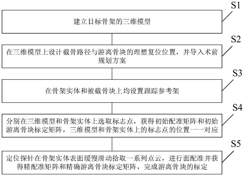
[0035] A calibration device for real-time tracking of the position of free bone fragments, such as figure 1 shown, including:

[0036] Step S1: Establish a 3D model of the target skeleton: perform image segmentation and 3D reconstruction based on CT data to obtain a 3D model of the target;

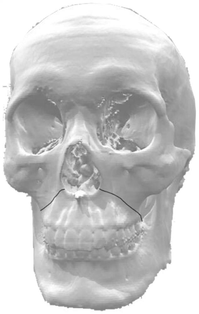
[0037] Step S2: if figure 2 As shown, the osteotomy path is designed on the 3D model, the free bone model is obtained through virtual cutting technology, and the cut bone is reset to the ideal position according to the 2D and 3D views, and the preoperative planning scheme is imported into the s...


PUM


Abstract

The invention relates to a calibration method for real-time tracking of the free bone block position. The calibration method is characterized by comprising the steps that S1, a three-dimensional modelof a target skeleton is established; S2, the osteotomy path and the ideal reposition position of a free bone block are designed on the three-dimensional model, and a preoperative planning scheme is introduced; S3, tracking reference frames are arranged on a skeleton entity and a truncated bone block correspondingly; S4, mark points are selected on the three-dimensional model and the skeleton entity correspondingly, an initial registration matrix and an initial free bone block calibration matrix are obtained, and the mark points on the three-dimensional model and the skeleton entity correspondin a one-to-one mode in position; and S5, a positioning probe slowly slides on the surface of the skeleton entity to pick up a series of point clouds, surface registration is conducted, a precision registration matrix and an accurate free bone block calibration matrix are obtained, and calibration of the free bone block is completed. Compared with the prior art, through the calibration method ofpoint and surface combination, the calibration accuracy can be effectively improved, and injury to a patient is reduced.

Description

technical field [0001] The invention relates to a calibration technology, in particular to a calibration device for real-time tracking of the position of a free bone block. Background technique [0002] In clinical repair and reconstruction surgery, the precise positioning of free bone fragments is crucial to the success of surgery. For example, in the diagnosis and treatment of dentofacial deformities, orthognathic surgery involves changes in the three maxillofacial structures (jawbone, facial soft tissue, and the occlusal relationship of the dentition), and small deviations in the restoration of free bone blocks may seriously affect the appearance. Bring lifelong pain to patients. Although the traditional use of osteotomy guides can assist doctors in determining the three-dimensional spatial relationship of the patient's maxillofacial teeth, the design and fabrication process is cumbersome, consuming a lot of time and energy for medical staff, and it is difficult to accur...

Claims


Application Information

Patent Timeline
Patent Type & Authority Patents(China)
IPC IPC(8): A61B34/10A61B34/20
CPCA61B34/10A61B34/20A61B2034/105A61B2034/107A61B2034/108A61B2034/2059A61B2034/2068
Inventor 陈晓军胡俊磊徐律
Owner SHANGHAI JIAOTONG UNIV
Why Eureka
Try Eureka