LSC compensation method and device of fisheye camera, and readable storage medium

A compensation method and camera technology, which is applied in the field of camera calibration, can solve problems such as LSC data deviation, abnormal color of image edge, and effect effects, so as to ensure accurate and consistent results

Active Publication Date: 2018-10-12
TRULY OPTO ELECTRONICS
View PDF6 Cites 1 Cited by
  • Summary
  • Abstract
  • Description
  • Claims
  • Application Information

AI Technical Summary

Problems solved by technology

According to the LSC compensation algorithm on the mobile phone platform, the optical center shift of the fisheye camera will directly affect the effect of LSC compensation
When the optical center shift is too large, it will cause abnormal color at the edge of the image
However, in the production process of the fisheye camera, the deviation of the optical center is unavoidable.
[0004] When the existing fisheye camera performs LSC compensation before leaving the factory, the LSC data will be calculated based on the center area of ​​the original image. The optical center shift will cause the optical center area to deviate from the physical center area, so that when calculating the LSC data, each value The regional proportion has changed, resulting in a large deviation in the final LSC data

Method used


Image

  • LSC compensation method and device of fisheye camera, and readable storage medium
  • LSC compensation method and device of fisheye camera, and readable storage medium
  • LSC compensation method and device of fisheye camera, and readable storage medium

Examples


Embodiment 1

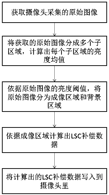
[0039] like figure 1 Shown, a kind of LSC compensation method of fisheye camera, including:

[0040] Step 1: Obtain the original image collected by the camera;

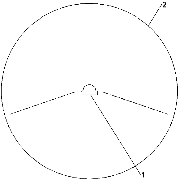
[0041] In this step 1, after the fisheye camera is electrically connected to the LSC compensation device, the fisheye camera is powered and driven by the LSC compensation device to shoot, and the original image in RAW format is obtained; preferably as follows figure 2 As shown, when shooting, the fisheye camera 1 is placed in a light source device having a spherical inner light emitting surface 2 , and the fisheye camera 1 is located on the center of the spherical inner light emitting surface 2 .

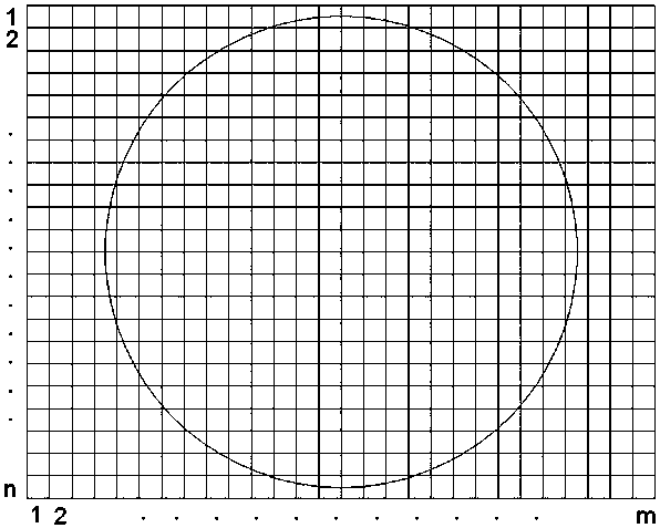
[0042] Step 2: Divide the obtained original image into multiple sub-regions, and calculate the brightness mean value of each sub-region;

[0043] In step 2, the average value of the brightness values ​​of all the bright spots in each sub-region is used as the average brightness value of the sub-region. preferably as i...

Embodiment 2

[0069] like Figure 4 As shown, an LSC compensation device for a fisheye camera includes a processor and a memory electrically connected to the processor, the memory stores a computer program for the processor to execute, and the processor executes the computer During the program, the LSC compensation method of the fisheye camera described in the first embodiment is carried out.

Embodiment 3

[0071] A readable storage medium stores a computer program for execution by a processor. When the computer program is executed by the processor, the processor performs the LSC compensation method for the fisheye camera described in Embodiment 1.


PUM


Abstract

The invention discloses an LSC compensation method and device for a fisheye camera, and a readable storage medium. The LSC compensation method comprises the following steps: step 1: obtaining an original image collected by the camera; step 2: dividing the obtained original image into a plurality of subareas, and calculating a brightness mean value of each subarea; step: 3: dividing the original image into an imaging area and a background area according to a brightness threshold of the original image, wherein the subarea in which the brightness mean value is greater than the brightness threshold is the imaging area, and the subarea in which the brightness mean value is less than the brightness threshold is the background area; step 4: calculating LSC compensation data according to the imaging area; and step 5: writing the calculated LSC compensation data into the camera. According to the LSC compensation method, the LSC data are calculated by using the imaging area, so no influence isgenerated to the value area during the calculation of the LSC data even in the presence of an optical center shift problem, thus ensuring the accuracy and consistency of the LSC data.

Description

technical field [0001] The invention relates to the field of camera calibration, in particular to an LSC compensation method and device for a fisheye camera, and a readable storage medium. Background technique [0002] A fisheye camera is a special camera with a field of view of 180° or more. It is often used as a surveillance camera to achieve a wide range of views. With the development of applications such as virtual reality technology and panoramic cameras, the use of fisheye cameras on smart terminals The application is also more and more extensive. [0003] LSC refers to lens vignetting correction, and the vignetting compensation effect of the fisheye camera directly affects the subsequent image fusion effect. According to the LSC compensation algorithm on the mobile phone platform, the optical center shift of the fisheye camera will directly affect the effect of LSC compensation. When the optical center shift is too large, it will cause abnormal color at the edge of ...

Claims


Application Information

Patent Timeline
Patent Type & Authority Applications(China)
IPC IPC(8): H04N5/235H04N5/357
CPCH04N23/71H04N25/60
Inventor 张博李建华
Owner TRULY OPTO ELECTRONICS
Why Eureka
Try Eureka