
Infrared camera parameter calibration plate

A camera parameter and calibration board technology, applied in the field of optical measurement, can solve the problems affecting the calibration accuracy of camera parameters, inability to accurately obtain the position of the center of the circle, and different luminous intensity, and achieve stable luminous intensity, moderate luminous intensity, and uniform luminous intensity. Effect

Pending Publication Date: 2018-10-12
广东省医疗器械质量监督检验所
View PDF0 Cites 2 Cited by
  • Summary
  • Abstract
  • Description
  • Claims
  • Application Information

AI Technical Summary

Problems solved by technology

The calibration plate that uses full-spectrum luminescent lamps for active luminescence will have different luminous intensities. When the intensity is too high, the size of the round hole on the calibration image does not match the size of the actual calibration plate, and the position of the center of the circle cannot be accurately obtained. Affects the calibration accuracy of camera parameters

Method used


Image

  • Infrared camera parameter calibration plate
  • Infrared camera parameter calibration plate
  • Infrared camera parameter calibration plate

Examples


Embodiment Construction

[0021] The patent solution will be further described below in conjunction with the accompanying drawings.

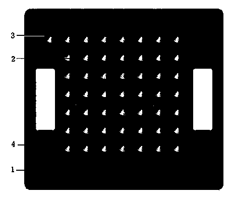
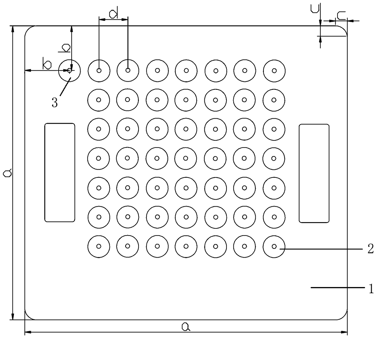
[0022] Such as figure 1 As shown, a near-infrared camera parameter calibration board includes a light-tight substrate 1, and the substrate 1 is provided with an array of circular holes M×N, vertical in rows and columns, and also includes a positioning hole 3, and the positioning hole 3 is set At one corner of the circular hole array, a reflective cloth 4 is arranged in the circular hole 2 in the circular hole array.

[0023] A near-infrared camera parameter calibration board provided by this patent includes a base plate 1 on which a circular hole array M×N is provided. For the convenience of calibration, the circular holes 2 of the circular hole array are evenly distributed on the substrate, and each circular hole 2 There is a fixed distance between them. A reflective cloth 4 is arranged in the round hole 2, and the patent uses the reflective cloth 4 for passive reflec...


PUM


Abstract

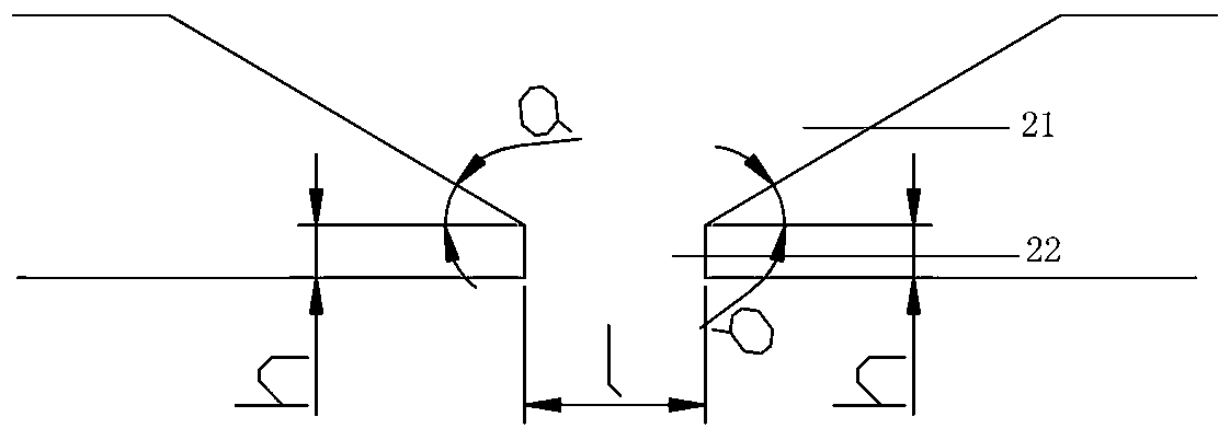
The invention relates to the field of optical measurement, and in particular relates to an infrared camera parameter calibration plate. The infrared camera parameter calibration plate comprises a lighttight substrate, wherein a round hole array M*N is arranged on the substrate, and the rows and columns are perpendicular. The infrared camera parameter calibration plate is characterized by also comprising a positioning hole, wherein the positioning hole is arranged at one corner of the round hole array, and reflecting cloth is arranged in round holes of the round hole array. The substrate is a square aluminum alloy plate with a certain thickness, and thus is not prone to deform. From the surface of the substrate to the position that is 0.01mm-0.5mm away from the back of the substrate, the diameters of the round holes are gradually reduced from the surface to the inside along the thickness direction of the substrate. The invention aims at providing the passive light emitting infrared light source calibration plate that is simple in structure, convenient to use, high in manufacturing accuracy and long in service life, and can accurately calibrate the internal and external parameters ofthe infrared camera.

Description

technical field [0001] This patent relates to the field of optical measurement, in particular to a near-infrared camera parameter calibration board. Background technique [0002] In optical measurement and positioning applications, the acquisition of internal and external parameters of the camera in the measurement system directly determines the measurement and positioning accuracy. The process of using the calibration device and calibration method to determine these parameters is called camera calibration. Therefore, how to accurately calibrate the camera has always been a research hotspot. On the one hand, the calibration algorithm is continuously improved and perfected, on the other hand, an accurate calibration board is designed. If the calibration plate is inaccurate, no matter what the calibration algorithm is, accurate calibration results cannot be obtained. Therefore, the design accuracy of the near-infrared calibration board is a key factor affecting the near-infr...

Claims


Application Information

Patent Timeline
Patent Type & Authority Applications(China)
IPC IPC(8): G06T7/80
CPCG06T7/80
Inventor 宋盟春黄鸿新陈婷伍倚明武晗杨荣骞
Owner 广东省医疗器械质量监督检验所
Learn More