
Lifting ejection rod with screw rod

A technology of ejector rods and screw rods, applied in the direction of lifting devices, etc., can solve the problems of easy failure of the mechanism, difficult maintenance work, high cost, etc., and achieve the effect of high operational reliability of the mechanism, low difficulty of maintenance work, and low product cost

Pending Publication Date: 2018-10-12
宁夏国励汽车动力科技有限公司
View PDF4 Cites 0 Cited by
  • Summary
  • Abstract
  • Description
  • Claims
  • Application Information

AI Technical Summary

Problems solved by technology

[0002] At present, the lifting technology of known lifting devices is mainly hydraulic lifting, pneumatic lifting and electronic lifting technology. This type of technology mainly uses hydraulic transmission or pneumatic transmission or electronic control transmission technology to play the role of lifting. The weak point of this type of technology is : There are many control components and complex structure. Working for a long time in harsh environments such as water, corrosive liquids, and high temperatures, the mechanism is prone to failure, low reliability, and maintenance is difficult and costly.

Method used


Image

  • Lifting ejection rod with screw rod

Examples


Embodiment Construction

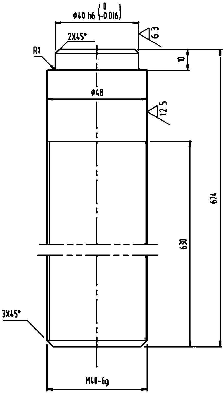
[0008] The screw lifting ejector rod is composed of three parts: the screw, the polished rod and the ejector head. The screw is in the lower part, the polished rod is in the middle, and the ejector head is in the upper part. The outer diameter of the lead screw is equal to that of the polished rod. The parameters of the lead screw are M48 thread and 630mm in length; the outer diameter of the polished rod is ¢48mm and the length is 34mm; A fixed nut cooperates, and the head of the ejector rod cooperates with the center hole of the lifting frame. When the screw is rotated, the screw moves up and down along the helical line of the nut, thereby jacking up or lowering the object.


PUM


Abstract

The invention discloses a lifting ejection rod with a screw rod. The lifting ejection rod with the screw rod is used for lifting an object through spiral line motion. The lifting ejection rod consistsof three parts including a lead screw, a polish rod and an ejection rod head, wherein the lead screw is arranged on the lower part; the polish rod is arranged in the middle; the ejection rod head isarranged on the upper part; the lead screw is matched with one fixed nut and the ejection rod head is matched with a central hole of a lifting rack; and when the lead screw is rotated, the lead screwis lifted along a spiral line of the nut so as to jack up or descend the object.

Description

technical field [0001] The invention relates to a lifting mandrel of a scraper transmission mechanical lifting device, in particular to a screw mandrel lifting mandrel which utilizes its own helical wire to play a lifting role. Background technique [0002] At present, the lifting technology of known lifting devices is mainly hydraulic lifting, pneumatic lifting and electronic lifting technology. This type of technology mainly uses hydraulic transmission or pneumatic transmission or electronic control transmission technology to play the role of lifting. The weak point of this type of technology is : There are many control components and complex structure, and it works for a long time under harsh environments such as water, corrosive liquid and high temperature, the mechanism is easy to fail, the reliability is low, and the maintenance work is difficult and the cost is high. Contents of the invention [0003] In order to overcome the deficiencies of the existing ejector tec...

Claims


Application Information

Patent Timeline
IPC IPC(8): B66F3/08
CPCB66F3/08
Inventor 李国强
Owner 宁夏国励汽车动力科技有限公司
Learn More