
Electric vehicle charging system

A charging system and technology for electric vehicles, applied in electric vehicle charging technology, electric vehicles, charging stations, etc., can solve the problem of non-electric vehicles being unusable, and achieve the effects of low cost, simple and convenient use, and simple production.

Inactive Publication Date: 2018-10-12
施成霞
View PDF0 Cites 0 Cited by
  • Summary
  • Abstract
  • Description
  • Claims
  • Application Information

AI Technical Summary

Problems solved by technology

Traditionally, electric vehicle AC charging piles can only charge electric vehicles, and non-electr

Method used


Image

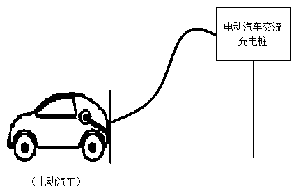
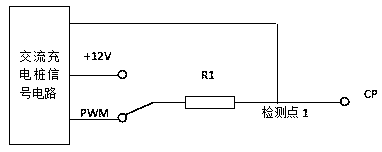
  • Electric vehicle charging system
  • Electric vehicle charging system
  • Electric vehicle charging system

Examples


Embodiment Construction

[0020] The following will clearly and completely describe the technical solutions in the embodiments of the present invention with reference to the accompanying drawings in the embodiments of the present invention. Obviously, the described embodiments are only some, not all, embodiments of the present invention. Based on the embodiments of the present invention, all other embodiments obtained by persons of ordinary skill in the art without creative efforts fall within the protection scope of the present invention.

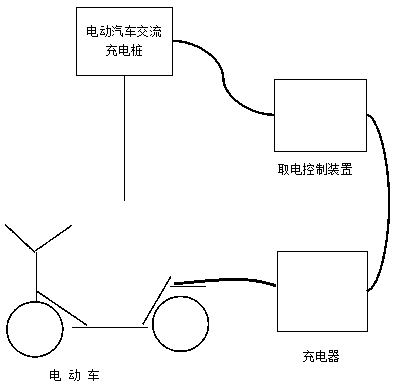
[0021] Such as image 3 As shown, the present invention provides an electric vehicle charging system, including a power-taking control device, one end of the power-taking control device is connected to an electric vehicle AC charging pile interface, and the other end is connected to a battery car charger, and the power-taking control device is taken out from the AC charging pile. AC power, supplied to the charger for charging.

[0022] Such as Figure 4 As shown,...


PUM


Abstract

The invention discloses a system. The system obtains a standard 220 V power supply from the alternating current charging pile end of an electric vehicle to provide the power supply for a charger of the electric vehicle so as to charge a storage battery of the electric vehicle (not an electric car). The system is simple and easy to use, low in cost and capable of being popularized on a large scale.

Description

technical field [0001] The invention belongs to the technical field of electric vehicle charging, and relates to a charging method, in particular to an electric vehicle (non-electric vehicle) charging system. Background technique [0002] Electric vehicles (non-electric vehicles such as electric bicycles and electric tricycles) are favored by people because of their cheap price, low operating costs, and environmental protection. The commonly used charging method for electric vehicles is to use the charger to connect to a 220V charging socket to obtain electric energy to charge the battery. However, there is no AC power interface outdoors, and it is very difficult to charge electric vehicles outdoors. Traditionally, it can only be charged by DC chargers outdoors, but the number of DC chargers is small, and due to the large charging current, they cannot be commonly used. [0003] At present, electric vehicles are welcomed by consumers due to their environmental protection, lo...

Claims


Application Information

Patent Timeline
IPC IPC(8): B60L11/18
CPCB60L53/14B60L53/60Y02T10/70Y02T10/7072Y02T90/12Y02T90/14
Inventor 施成霞李文勇
Owner 施成霞
Learn More