
Drilling machine for improving drilling effect

A drilling machine and servo motor technology, applied in metal processing and other directions, can solve problems such as shoe damage, worker injury, pollution of the working environment, etc., and achieve the effect of strengthening the fixing effect, reducing potential safety hazards, and preventing debris from splashing.

Inactive Publication Date: 2018-10-12
林碧琴
View PDF0 Cites 0 Cited by
  • Summary
  • Abstract
  • Description
  • Claims
  • Application Information

AI Technical Summary

Problems solved by technology

[0002] At present, shoes have a long history. About 5,000 years ago, the most primitive shoes made of animal skins appeared. Shoes are a tool for people to protect their feet from injury. Fur shoes were invented because of discomfort or injury. The shoes have developed to the present, and shoes of various styles and functions can be seen everywhere. During the production process, the soles of flip-flops need to be drilled. The drilled holes used Generally, it is realized by a drilling machine, but the existing drilling device will generate high temperature after working for a long time, which may damage the drill bit or reduce the drilling accuracy, affect the production quality of shoes, and the debris produced by drilling is chaotic. Splashing may cause certain injuries to workers and pollute the working environment. In addition, when drilling holes, it is necessary to fix the shoes first and then drill holes. The positioning effect of existing drilling devices is not good, and most of them are fixed by extrusion. Excessive force will cause damage or deformation of the shoes, and small extrusion force will cause sliding during drilling, which will affect the drilling effect. In view of this, the designer actively studies it in order to create a drilling machine that can improve the drilling effect. to solve the above problems

Method used


Image

  • Drilling machine for improving drilling effect
  • Drilling machine for improving drilling effect
  • Drilling machine for improving drilling effect

Examples


Embodiment Construction

[0015] The following will clearly and completely describe the technical solutions in the embodiments of the present invention with reference to the accompanying drawings in the embodiments of the present invention. Obviously, the described embodiments are only some, not all, embodiments of the present invention. Based on the embodiments of the present invention, all other embodiments obtained by persons of ordinary skill in the art without making creative efforts belong to the protection scope of the present invention.

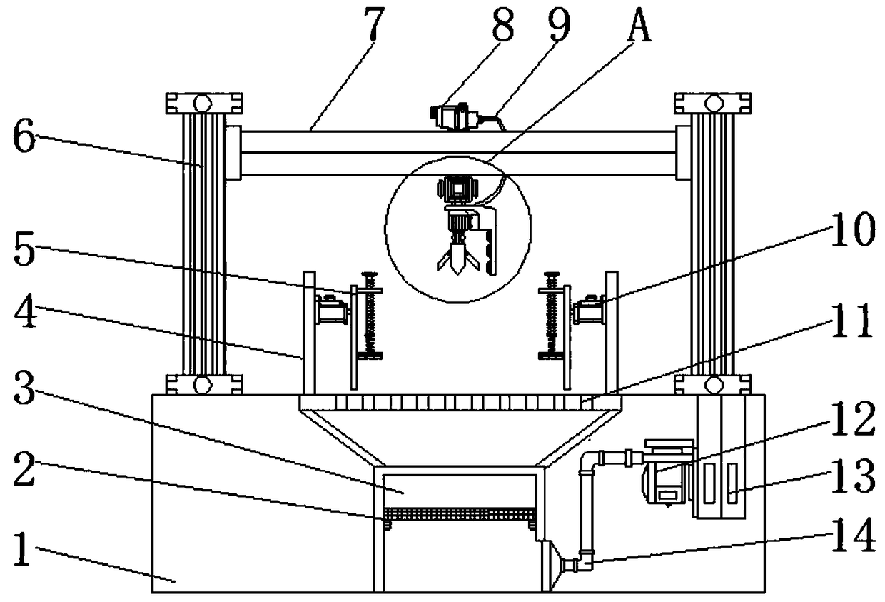
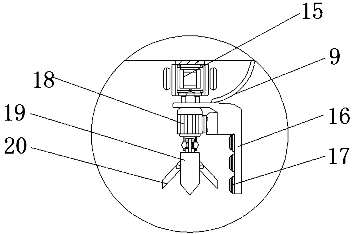
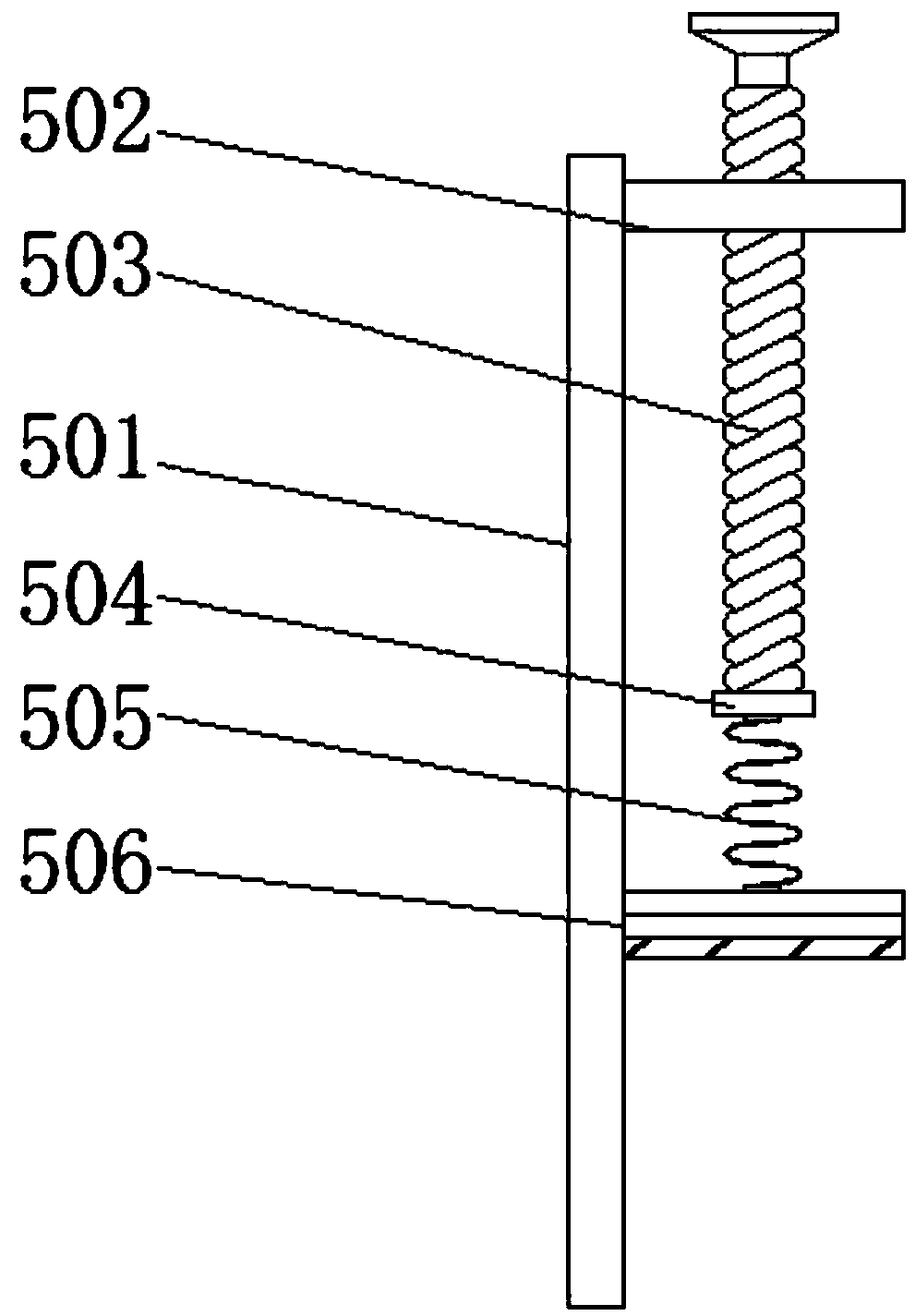
[0016] see Figure 1-3 , an embodiment provided by the present invention: a drilling machine for improving the drilling effect, including a workbench 1, a mounting plate 4 is symmetrically arranged at the middle position of the top of the workbench 1, and the opposite sides of the two mounting plates 4 are both A hydraulic cylinder 10 is provided. The model of the hydraulic cylinder 10 can be C25WE80. The output end of the hydraulic cylinder 10 is equipped wit...


PUM


Abstract

The invention discloses a drilling machine for improving the drilling effect. The drilling machine comprises a working table, installing plates are symmetrically arranged at the middle position of thetop of the working table, hydraulic cylinders are arranged on the opposite sides of the two installing plates, the output ends of the hydraulic cylinders are provided with fixing assemblies, and eachfixing assembly comprises a supporting plate, an extending plate, a screw, an elastic gasket, a buffer spring and a limiting block, wherein the extending plate is installed at the top of the side, far away from the corresponding hydraulic cylinder, of the supporting plate, a threaded hole is formed in the extending plate and is provided with the screw, the screw penetrates the extending plate, extends to the lower portion of the extending plate and is provided with the elastic gasket, the buffer spring is arranged at the bottom of the elastic gasket, and the limiting block is arranged at theother end of the buffer spring. Compared with an existing like product, the drilling accuracy is high, the applicability is high, environmental protection is better achieved, and enterprise use and popularization are facilitated.

Description

technical field [0001] The invention relates to the field of shoe production equipment, in particular to a drilling machine for improving the drilling effect. Background technique [0002] At present, shoes have a long history. About 5,000 years ago, the most primitive shoes made of animal skins appeared. Shoes are a tool for people to protect their feet from injury. Fur shoes were invented because of discomfort or injury. The shoes have developed to the present, and shoes of various styles and functions can be seen everywhere. During the production process, the soles of flip-flops need to be drilled. The drilled holes used Generally, it is realized by a drilling machine, but the existing drilling device will generate high temperature after working for a long time, which may damage the drill bit or reduce the drilling accuracy, affect the production quality of shoes, and the debris produced by drilling is chaotic. Splashing may cause certain injuries to workers and pollute ...

Claims


Application Information

Patent Timeline
Patent Type & Authority Applications(China)
IPC IPC(8): B26F1/16B26D7/00B26D7/01B26D7/18
CPCB26F1/16B26D7/00B26D7/01B26D7/1863
Inventor 林碧琴
Owner 林碧琴
Learn More