This helps you quickly interpret patents by identifying the three key elements:
Problems solved by technology
Method used
Benefits of technology
Problems solved by technology
[0003] It has been seen in practice that this long-established structural form is increasingly unable to meet the growing requirements for such electrical devices, especially electric heating devices, and has reached its limit
Method used
Image
Click on the blue label to locate the original text in one second.
Reading with bidirectional positioning of images and text.
Examples
Embodiment Construction
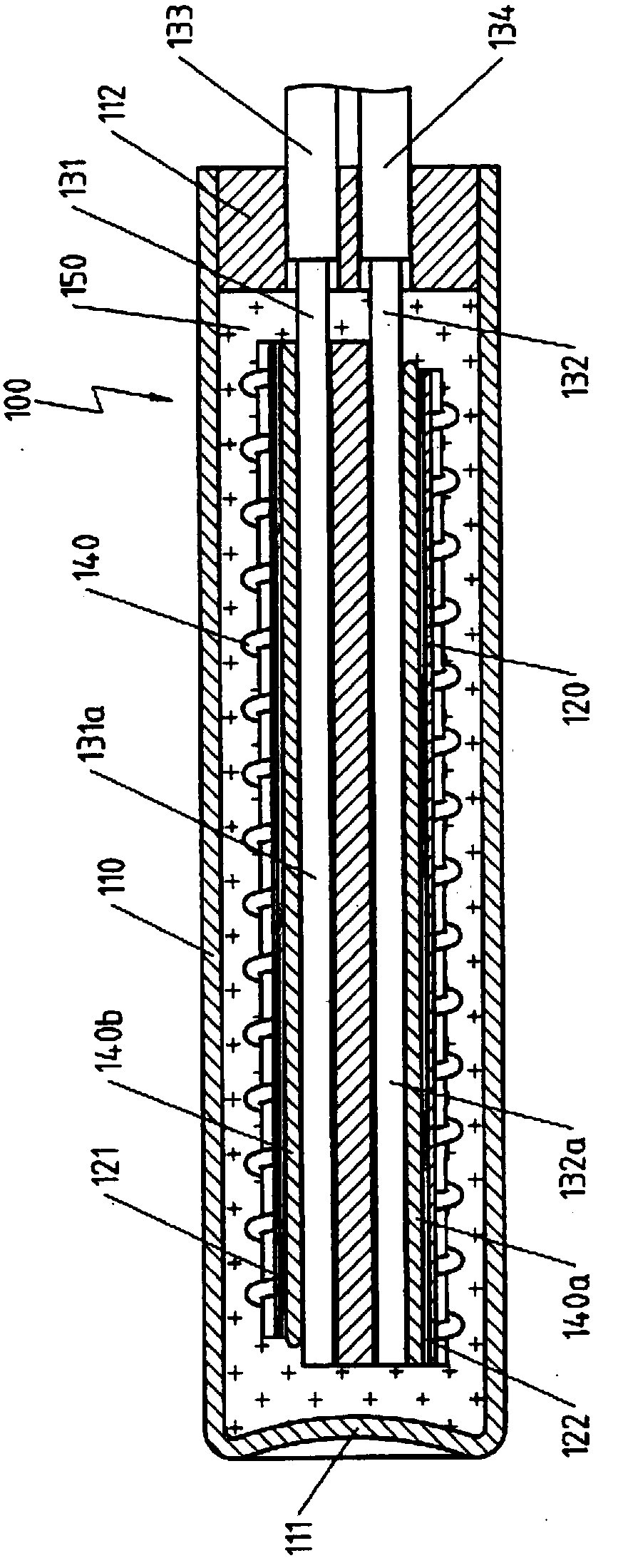
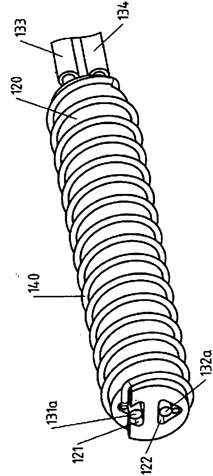
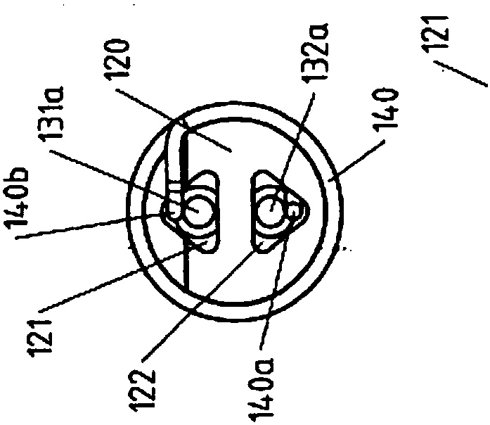
[0051] Figure 1a Shown is an electrical device 100 implemented as a heating cartridge having a tubular metal sheath 110 with a bottom 111 and an insulator 120 arranged inside the tubular metal sheath 110 and embedded in an electrically insulating material 150 such as MgO. At the end of the tubular metal sheath 110 opposite the bottom 111 , the power supply lines 133 , 134 are led through the plug 112 . as well Figure 1b and 1c As shown, two tunnel-like openings 121 , 122 pass through the insulator 120 . The respective sections 131 a , 132 a of the first electrical conductors 131 , 132 formed by the current-carrying wires of the supply lines 133 , 134 are received in the tunnel-like openings 121 , 122 .
[0052] A second electrical conductor 140 , ie the heating element, is wound externally on the insulator 120 , the ends 140 a , 140 b of this second electrical conductor 140 likewise running parallel to the sections 131 a , 132 a of the first electrical conductors 131 , 13...
PUM
Abstract
An electrical device (100,200) is provided having a tubular metal sheath (110,210,250,260) and an insulator (120,160,220,251,261), the insulator (120,160,220,251,261) is arranged inside the tubular metal sheath (110,210,250,260), and at least one tunnel-shaped opening (121,122,161, 162,221,252,262) penetrates through the insulator (120,160,220,251,261), wherein at least one section (131a,132a,171a,172a) of the first electrical conductor (131,132,171,172,231) is arranged in the tunnel-shaped opening(121,122,161,162,221,252,262),wherein the cross section geometrical shape of the tunnel-shaped opening (121, 122, 161,162,221,252,262) deviates from a circle.
Description
technical field [0001] The invention relates to an electrical device having the features stated in the preamble of patent claim 1 . Background technique [0002] Such electrical devices include, for example, sheathed thermocouples and electric heating cartridges, wherein the thermocouple legs or sections of the electric heating element, in particular resistance wires, are arranged in the bore of the winding body inside the tubular metal sheath, i.e. with a circular The tunnel-like openings of the cross-section of the holes extend and can also be connected indirectly or directly to connecting wires or connection lines inside these holes. [0003] It has been found in practice that this long-established construction is increasingly unable to meet the increasing demands placed on such electrical installations, especially electric heating installations, and reaches its limits. For example, ever-increasing heating output needs to be accommodated in ever-smaller spaces without co...
Claims
Application Information
Patent Timeline
Application Date:The date an application was filed.
Publication Date:The date a patent or application was officially published.
First Publication Date:The earliest publication date of a patent with the same application number.
Issue Date:Publication date of the patent grant document.
PCT Entry Date:The Entry date of PCT National Phase.
Estimated Expiry Date:The statutory expiry date of a patent right according to the Patent Law, and it is the longest term of protection that the patent right can achieve without the termination of the patent right due to other reasons(Term extension factor has been taken into account ).
Invalid Date:Actual expiry date is based on effective date or publication date of legal transaction data of invalid patent.