A transformer underground oil storage cooling compensation device with a flow divider

A compensation device, transformer oil technology, applied in the direction of transformer/inductor cooling, etc., can solve the problems of increased floor space, waste of resources, limited installation, etc., to meet the needs of use, reduce floor space, and oil storage. reduced effect

Pending Publication Date: 2018-10-09
沈阳海为电力装备股份有限公司
View PDF10 Cites 0 Cited by
  • Summary
  • Abstract
  • Description
  • Claims
  • Application Information

AI Technical Summary

Problems solved by technology

[0003] 1. The chip radiator communicates with the transformer oil tank, which increases the amount of transformer oil, and the cost is high; at the same time, the chip and water-cooled radiators are installed around the transformer, which increases the floor space and makes installation inconvenient
[0004] 2. The oil conservator is generally installed on the upper part or one end of the transformer, and the larger size affects the insulation distance of the transformer; especially the installation in the tunnel is limited, which has certain limitations
[0005] 3. The oil conservator is located at a higher position of the transformer, which makes installation, oil filling and maintenance inconvenient and unsafe; in addition, the temperature of the oil stored in the oil conservator is lower than that of the transformer, but it does not flow, resulting in waste of resources
[0006] 4. Once an accident occurs, it is easy to cause pollution to the environment, which is not conducive to environmental protection, and the maintenance of each component increases the operating cost

Method used


Image

  • A transformer underground oil storage cooling compensation device with a flow divider

Examples


Embodiment Construction

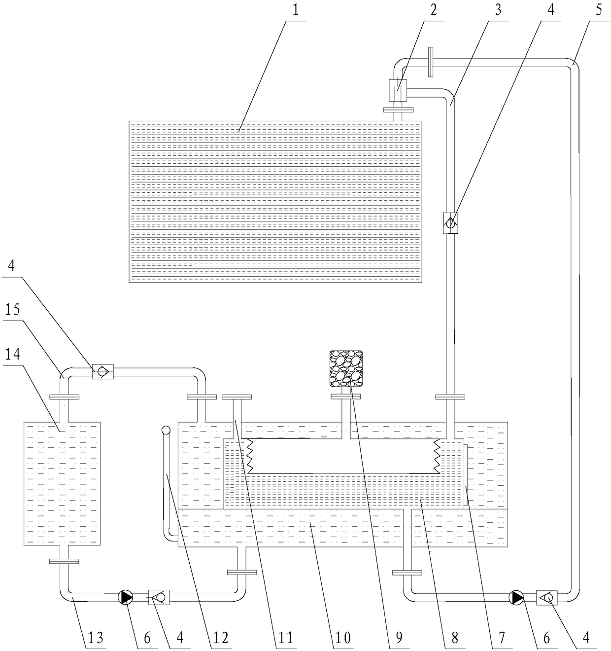
[0018] The present invention will be described in further detail below in conjunction with the accompanying drawings.

[0019] Such as figure 1 As shown, the present invention includes a corrugated oil conservator 8, a liquid circulation tank 10, a liquid cooling tank 14, a cooling liquid circulation pipeline and a transformer oil circulation pipeline, wherein the liquid circulation tank 10 and the liquid cooling tank 14 are respectively located under the transformer 1 , placed side by side, and all arranged below the ground, a corrugated oil conservator 8 is installed in the liquid circulation tank 10 . The cooling liquid circulation pipeline includes an upper circulation pipeline 15 and a lower circulation pipeline 13. The transformer oil circulation pipeline includes a hot oil circulation pipeline 3 and a cold oil circulation pipeline 5. The two ends of the upper circulation pipeline 15 are respectively connected to the liquid cooling pipeline. The top of the tank 14 commu...


PUM


Abstract

The invention relates to a transformer underground oil storage cooling compensation device with a flow divider. A liquid circulation box and a liquid cooling box are positioned under a transformer andare both arranged under the ground, and a corrugated oil conservator is installed in the liquid circulation box; a cooling liquid circulation pipeline includes an upper circulation pipeline and a lower circulation pipeline, and the liquid cooling box is connected with the liquid circulation box through the upper and lower circulation pipeline; a transformer oil circulation pipeline includes a hotoil circulation pipeline and a cold oil circulation pipeline, one end of the hot oil circulation pipeline and one end of the cold oil circulation pipeline are connected with the corrugated oil conservator, the other ends are connected with the flow divider, and the flow divider is communicated with the transformer; the lower circulation pipeline is provided with a non-return valve and a circulating pump used for controlling the circulation of the cooling liquid, the cold oil circulation pipeline is provided with a non-return valve and a circulating pump used for control the circulation of thecold and hot oil, and the upper circulation pipeline and the hot oil circulation pipeline are provided with the non-return valves. The transformer oil cooling and compensation are integrated, components are reduced, especially the quantity of oil storage is reduced, and the energy resource is saved.

Description

technical field [0001] The invention relates to a compensation device configured and used for an oil-immersed transformer and power equipment in a power system, in particular to a transformer underground oil storage cooling compensation device with a shunt valve. Background technique [0002] Currently, oil-immersed power transformers are equipped with radiator and oil conservator components, each of which has its own independent function for the transformer, and are installed above the ground. The radiator is installed around the transformer oil tank for heat dissipation of the transformer oil; the oil conservator is installed on the upper part or one end of the transformer oil tank to compensate for the volume change of the transformer oil. Because of its ground installation and independent function, there are the following problems: [0003] 1. The chip radiator communicates with the transformer oil tank, which increases the amount of transformer oil, and the cost is hig...

Claims


Application Information

Patent Timeline
Patent Type & Authority Applications(China)
IPC IPC(8): H01F27/14H01F27/10
CPCH01F27/10H01F27/14
Inventor 邵为
Owner 沈阳海为电力装备股份有限公司
Why Eureka
Try Eureka