A clutch device used for producing steel

A clutch device, steel technology, applied in auxiliary devices, auxiliary welding equipment, welding/cutting auxiliary equipment, etc., can solve the problems of difficult operation, complex structure, difficult installation and maintenance, etc., to achieve good safety performance, simple structure design, safety Performance and stable effects

Inactive Publication Date: 2018-10-09
陈亚龙
View PDF0 Cites 0 Cited by
  • Summary
  • Abstract
  • Description
  • Claims
  • Application Information

AI Technical Summary

Problems solved by technology

The existing clutch device for producing steel has the disadvantages of complex structure, difficult operation, difficult installation and maintenance, and is not suitable for industrialized large-scale production

Method used


Image

  • A clutch device used for producing steel

Examples


Embodiment Construction

[0011] The present invention will be further explained below in conjunction with the drawings and embodiments.

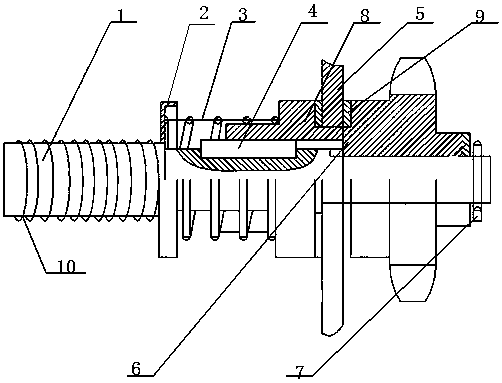
[0012] Such as figure 1 As shown, a clutch device for steel production includes a driving shaft 1, on which a pressure plate 2, a compression spring 3, a guide 4, a clutch pressure plate 5, a transmission gear 6 and a positioning pin 7 are sequentially sleeved, The clutch pressing plate 5 is fixedly connected by rivets 6, and an anti-wear sliding sleeve 8 is provided on the guide 4. An anti-wear pad 9 is provided outside the rivet 6, and the thickness of the anti-wear pad 9 is 1-4 mm. The pressure plate 2 or the clutch pressure plate 5 is made of high-temperature ceramic material, and the pressure plate 2 or the clutch pressure plate 5 is 2-3 cm. A number of reinforcing ribs 10 are provided on the driving shaft 1.

[0013] The invention has simple structure design, is suitable for large-scale industrial production, and has good safety performance and stability.

[0014...


PUM

PropertyMeasurementUnit
Thicknessaaaaaaaaaa

Abstract

The invention discloses a clutch device used for producing steel. The clutch device includes a driving shaft (1), the driving shaft (1) is sleeved by a pressure plate (2), a compression spring (3), adirection guider (4), a clutch pressure plate (5), a change-speed gear (6) and a positioning pin (7) in order, the clutch pressure plate (5) is fixedly connected through rivets (6), and a wear-preventive sliding sleeve (8) is arranged on the direction guider (4). The problem that the existing clutch means used for producing steel is complex in structure, difficult in operation, difficult in installation and influences beauty is effectively solved.

Description

Technical field [0001] The invention discloses a welding device, in particular to a clutch device for steel production. Background technique [0002] Steel structure is a structure mainly composed of steel materials and is one of the main types of building structures. The structure is mainly composed of steel beams, steel columns, steel trusses and other components made of section steel and steel plates. The components or parts are usually connected by welds, bolts or rivets. Because of its light weight and easy construction, it is widely used in large-scale factories, venues, super high-rise buildings and other fields. The existing clutch device for steel production has the disadvantages of complicated structure, difficult operation, difficult installation and maintenance, and not suitable for industrialized mass production. Summary of the invention [0003] The purpose of the present invention is to overcome the problems of the prior art and provide a clutch device for steel p...

Claims


Application Information

Patent Timeline
IPC IPC(8): B23K37/00
CPCB23K37/00
Inventor 陈亚龙
Owner 陈亚龙
Why Eureka
Try Eureka