Magnetic-lifting electric caldron
An electric cooker and magnetic technology, which is applied in the directions of plug-ins, cooker brackets, etc., can solve the problems of the inner pot and the main body of the machine being difficult to achieve separate design, the sealing device being easily damaged by aging, and the inability to achieve split cleaning, etc. The effect of flowing into the slide pipe, prolonging the service life and avoiding contamination of the soup
- Summary
- Abstract
- Description
- Claims
- Application Information
AI Technical Summary
Problems solved by technology
Method used
Image

Examples
Embodiment 1
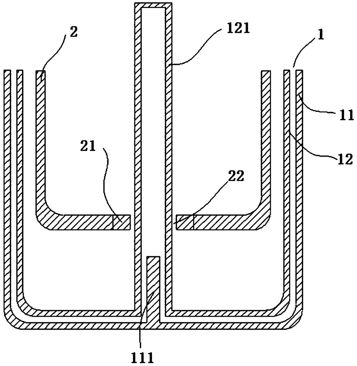
[0040] Such as figure 1 , a magnetic lifting electric cooking pot, characterized in that it includes an outer pot 1 and an inner pot 2 connected to the outer pot 1 through a magnetic lifting mechanism, the inner pot 2 is located in the outer pot 1, and the magnetic force The lifting mechanism includes a first magnetic device 111 arranged at the bottom of the outer pot 1 and a second magnetic device 21 arranged at the bottom of the inner pot 2 .
Embodiment 2
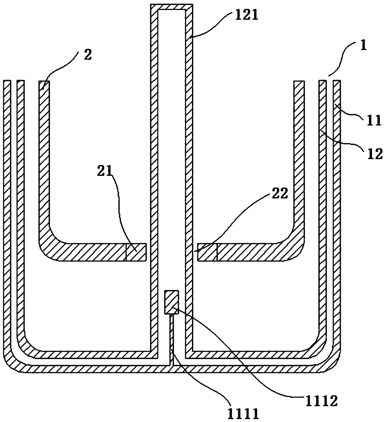
[0042] Such as figure 1 , a magnetic lifting electric cooking pot, characterized in that it includes an outer pot 1 and an inner pot 2 connected to the outer pot 1 through a magnetic lifting mechanism, the inner pot 2 is located in the outer pot 1, and the magnetic force The lifting mechanism includes a first magnetic device 111 arranged at the bottom of the outer pot 1 and a second magnetic device 21 arranged at the bottom of the inner pot 2 .
[0043] The outer pot 1 includes a bottom pot 11 and an inner pot 12, the inner pot 12 is located in the bottom pot 11, the first magnetic device 111 is arranged on the bottom surface of the bottom pot 11, and the inner pot 12 Corresponding to the first magnetic device 111 , a sliding tube 121 is arranged vertically, and the sliding tube 121 is sleeved on the first magnetic device 111 .
[0044] The bottom of the inner pot 2 is provided with a sliding hole 22 matched with the sliding tube 121, the sliding hole 22 is sleeved on the sli...
Embodiment 3
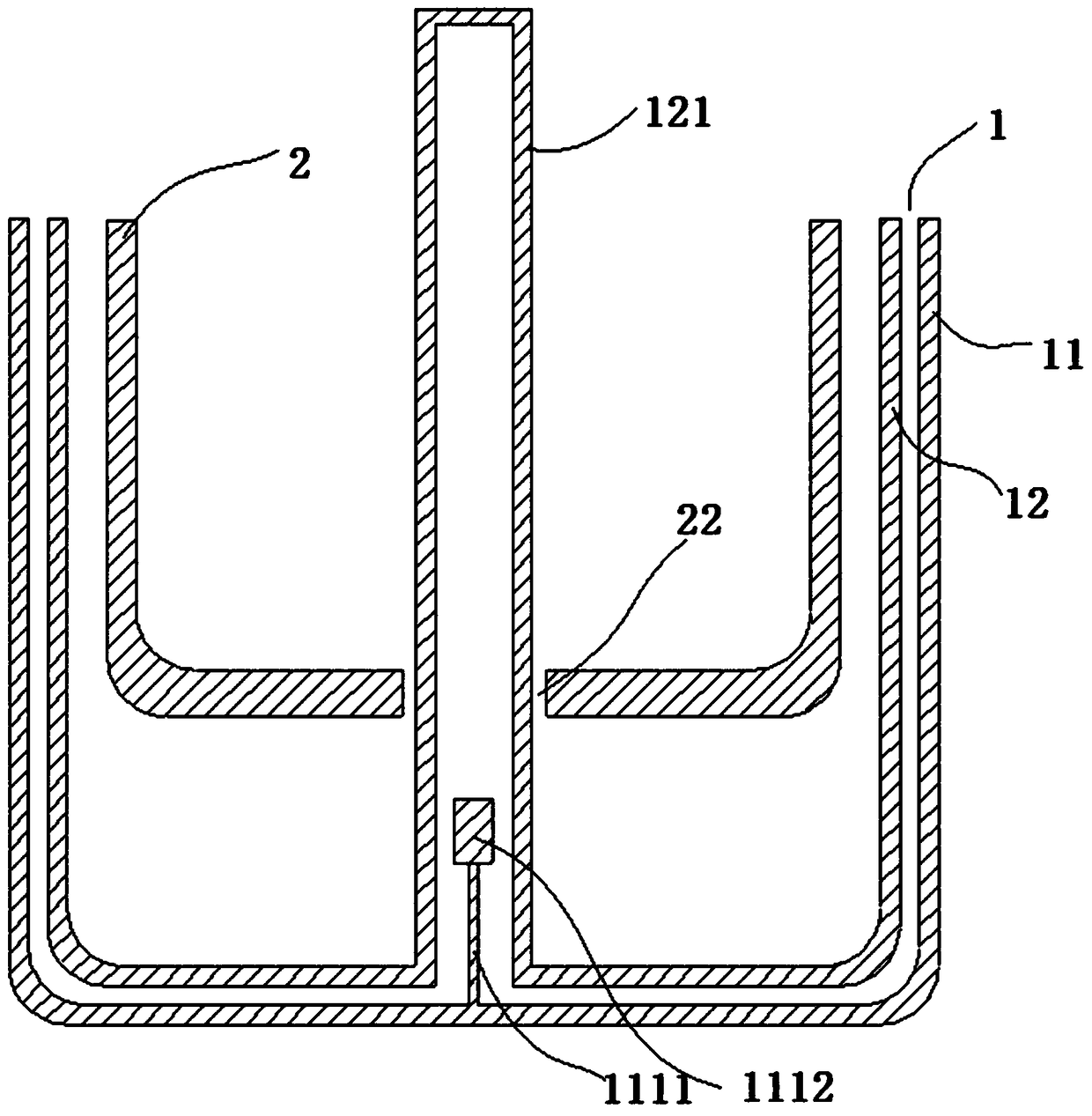
[0047] Such as figure 1 , a magnetic lifting electric cooking pot, characterized in that it includes an outer pot 1 and an inner pot 2 connected to the outer pot 1 through a magnetic lifting mechanism, the inner pot 2 is located in the outer pot 1, and the magnetic force The lifting mechanism includes a first magnetic device 111 arranged at the bottom of the outer pot 1 and a second magnetic device 21 arranged at the bottom of the inner pot 2 .
[0048] The outer pot 1 includes a bottom pot 11 and an inner pot 12, the inner pot 12 is located in the bottom pot 11, the first magnetic device 111 is arranged on the bottom surface of the bottom pot 11, and the inner pot 12 Corresponding to the first magnetic device 111 , a sliding tube 121 is arranged vertically, and the sliding tube 121 is sleeved on the first magnetic device 111 .
[0049] The bottom of the inner pot 2 is provided with a sliding hole 22 matched with the sliding tube 121, the sliding hole 22 is sleeved on the sli...
PUM
 Abstract
Description
Claims
Application Information
 - R&D
- Intellectual Property
- Life Sciences
- Materials
- Tech Scout
- Unparalleled Data Quality
- Higher Quality Content
- 60% Fewer Hallucinations
Browse by: Latest US Patents, China's latest patents, Technical Efficacy Thesaurus, Application Domain, Technology Topic, Popular Technical Reports.
© 2025 PatSnap. All rights reserved.Legal|Privacy policy|Modern Slavery Act Transparency Statement|Sitemap|About US| Contact US: help@patsnap.com