
Polarity testing method for differential protection of generator-transformer set

A polarity test and differential protection technology, applied in the electrical field, can solve problems such as heavy workload and risk, low test efficiency, and numerous test steps, and achieve the effect of reducing test time, improving test efficiency, and reducing test steps

Active Publication Date: 2018-10-02
CHINA SHENHUA ENERGY CO LTD +2
View PDF7 Cites 5 Cited by
  • Summary
  • Abstract
  • Description
  • Claims
  • Application Information

AI Technical Summary

Problems solved by technology

Normally, the short-circuit test should be completed in three times according to the normal steps, that is, short-circuit at the generator end, short-circuit at the low-voltage side of the main transformer, and short-circuit at the high-voltage side of the main transformer. The state of the equipment and the verification measures used at each short-circuit point are different, resulting in a large number of test steps, a large workload and risk, more time-consuming (about 15 hours), and low test efficiency.

Method used


Image

  • Polarity testing method for differential protection of generator-transformer set
  • Polarity testing method for differential protection of generator-transformer set
  • Polarity testing method for differential protection of generator-transformer set

Examples


Embodiment Construction

[0017] The specific implementation manners of the embodiments of the present invention will be described in detail below in conjunction with the accompanying drawings. It should be understood that the specific implementation manners described here are only used to illustrate and explain the embodiments of the present invention, and are not intended to limit the embodiments of the present invention.

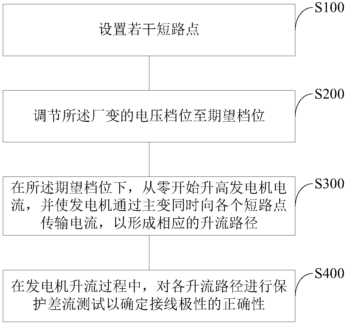
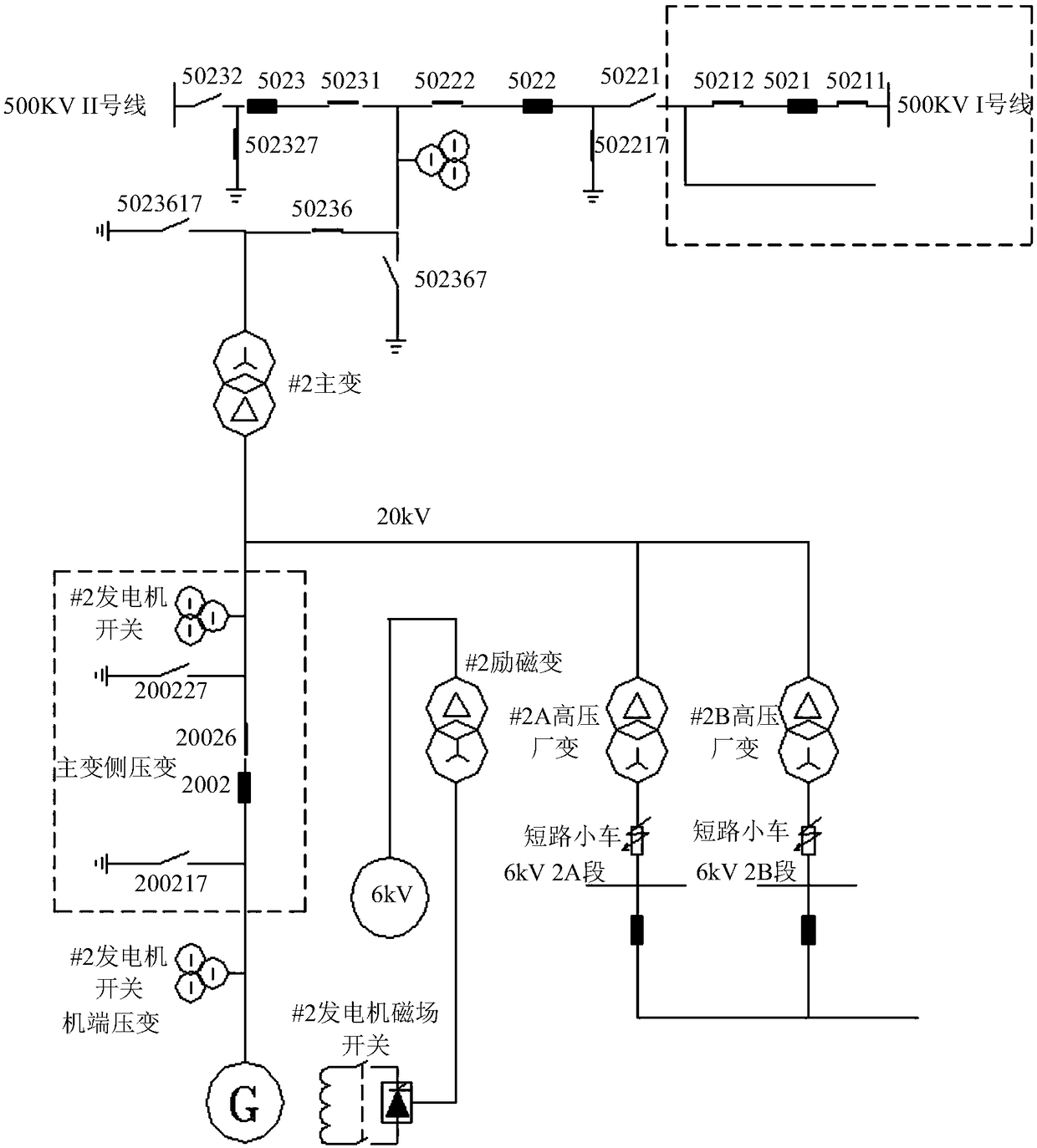
[0018] figure 1 It is a schematic flowchart of a polarity test method for differential protection of a generator-transformer set according to an embodiment of the present invention, where the generator-transformer set includes generators, main transformers, plant transformers, and corresponding switches, switch blades, and current transformer circuits. figure 2 It is the wiring diagram of the short-circuit test of the generator-transformer group in the embodiment of the present invention, and the structure of the generator-transformer group can also refer to figure 2 , the gene...


PUM


Abstract

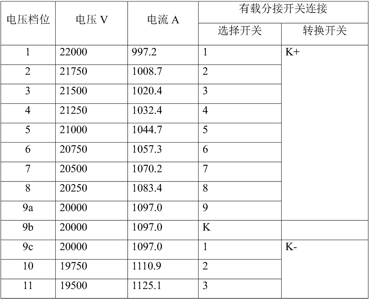
he embodiment of the invention, which belongs to the field of the electrical technology, provides a polarity testing method for differential protection of a generator-transformer set. The polarity testing method comprises: a plurality of short-circuit points are set; a gear of a factory transformer is adjusted to be an expected gear, wherein currents obtained from a generator by a factor transformer low-voltage side to a main transformer high-voltage side meet a connecting line polarity testing precision requirement based on the expected gear; the current of the generator is increased by starting with zero and the generator transmits currents to all short-circuit points simultaneously by the main transformer to form corresponding current increasing paths; and protection differential current testing is carried out on all current increasing paths to determine correctness of line connection polarities during the current increasing process of the generator. According to the invention, polarity testing of secondary circuits of all current transformers protected by the generator-transformer set can be completed by short-circuit testing once, so that the test steps and test time are reduced substantially and thus the costs are lowered; the workloads of the operation personnel and the maintenance personnel are reduced; and the test efficiency is improved.

Description

technical field [0001] The invention relates to the field of electrical technology, in particular to a polarity test method for differential protection of a generator-transformer unit. Background technique [0002] Generators and transformers (hereinafter referred to as generator-transformer units) are the main power generation and power transmission and transformation equipment in power stations. As the main protection for generator-transformer units, differential protection must be protected against differential protection current circuits ( Mainly check the integrity and polarity of the wiring of the current transformer circuit) to ensure that it is correct before it can be put into use, otherwise the differential protection may malfunction due to wrong wiring polarity when the generator-transformer equipment is running normally, or When the generator-transformer equipment fails, it refuses to move, causing the equipment to burn out, and at the same time causing great har...

Claims


Application Information

Patent Timeline
Patent Type & Authority Applications(China)
IPC IPC(8): G01R31/34
CPCG01R31/34
Inventor 向敏
Owner CHINA SHENHUA ENERGY CO LTD
Learn More