Spherical scanner and three-dimensional scanning system

A scanner and sphere technology, applied in the field of optical scanning, can solve problems such as cumbersome process of pasting reflective markers, inapplicability of high-precision equipment and cultural relics, precision measurement cannot meet the requirements, etc., to achieve expandable working space, simple structure, Aesthetically pleasing effect

Inactive Publication Date: 2018-10-02
ZG TECH CO LTD
View PDF4 Cites 10 Cited by
  • Summary
  • Abstract
  • Description
  • Claims
  • Application Information

AI Technical Summary

Problems solved by technology

[0002] 3D laser scanners have been able to conveniently solve most of the high-precision measurement tasks that do not require the surface texture of objects, but they must paste a certain number of evenly distributed reflective marker points on the surface of the object to be measured for frame splicing during scanning, while pasting reflective The process of marking points is cumbersome and takes a lot of time, which increases the workload of scanning and measurement, and is not suitable for high-value items such as high-precision equipment and cultural relics that do not allow marking points to be pasted on the surface
However, due to its algorithm mechanism, the accuracy cannot meet the needs of precise measurement, and its reconstruction results are highly ornamental, but it is not the best choice for scanning measurement

Method used


Image

  • Spherical scanner and three-dimensional scanning system
  • Spherical scanner and three-dimensional scanning system
  • Spherical scanner and three-dimensional scanning system

Examples


Embodiment Construction

[0039] The principles and features of the present invention are described below in conjunction with the accompanying drawings, and the examples given are only used to explain the present invention, and are not intended to limit the scope of the present invention.

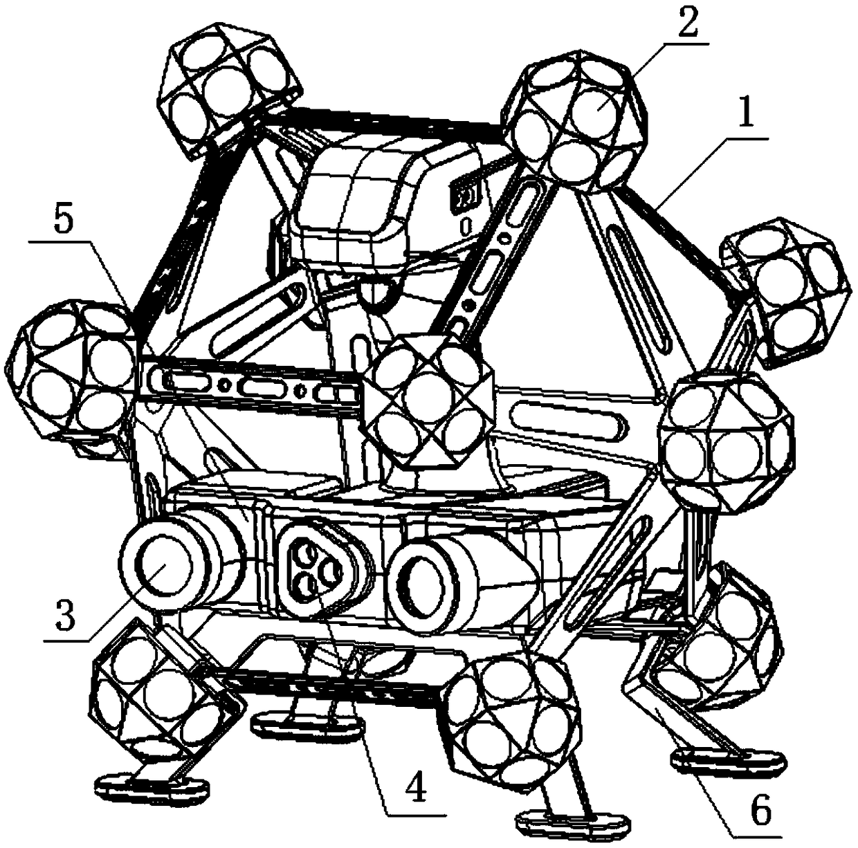
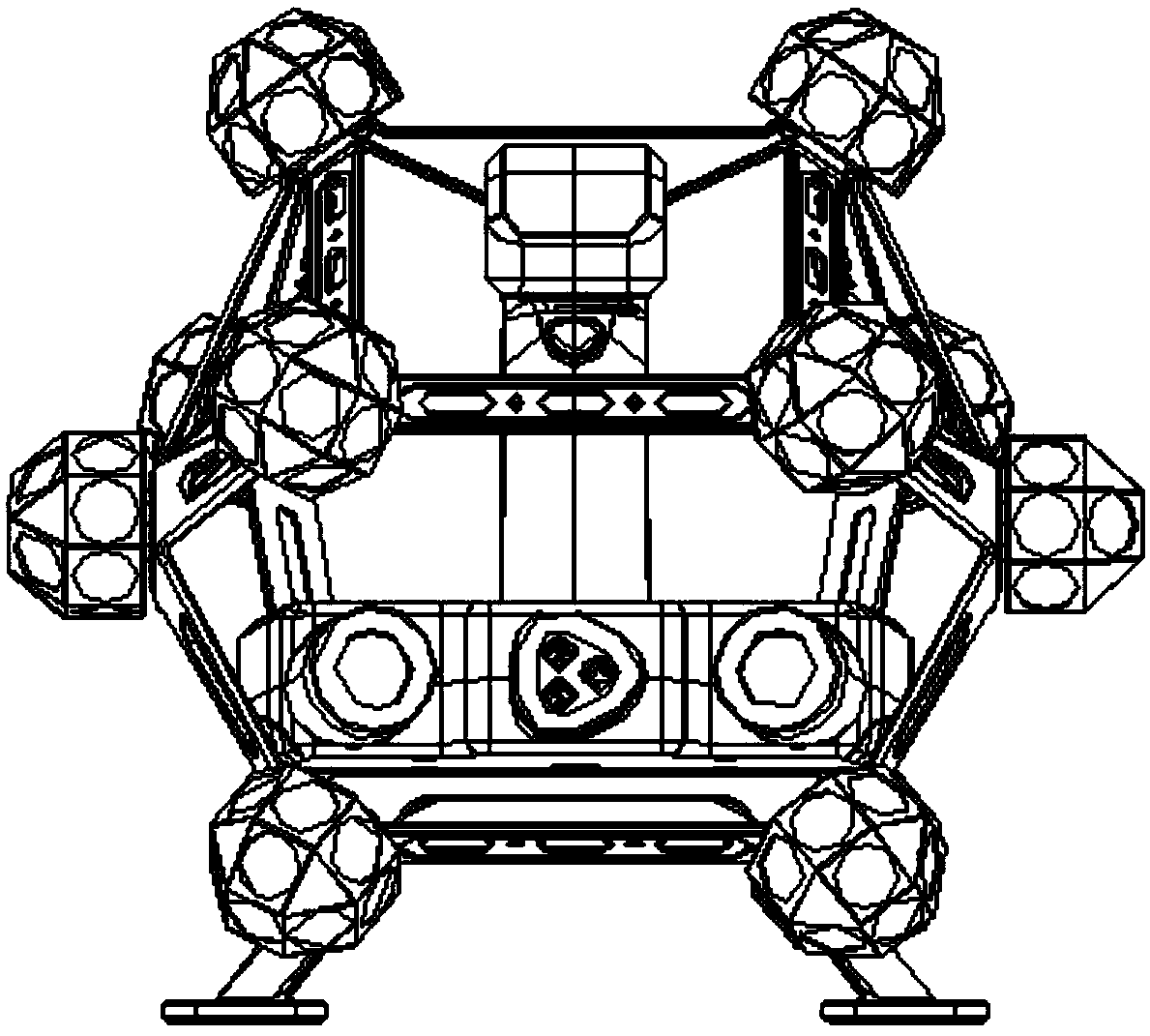
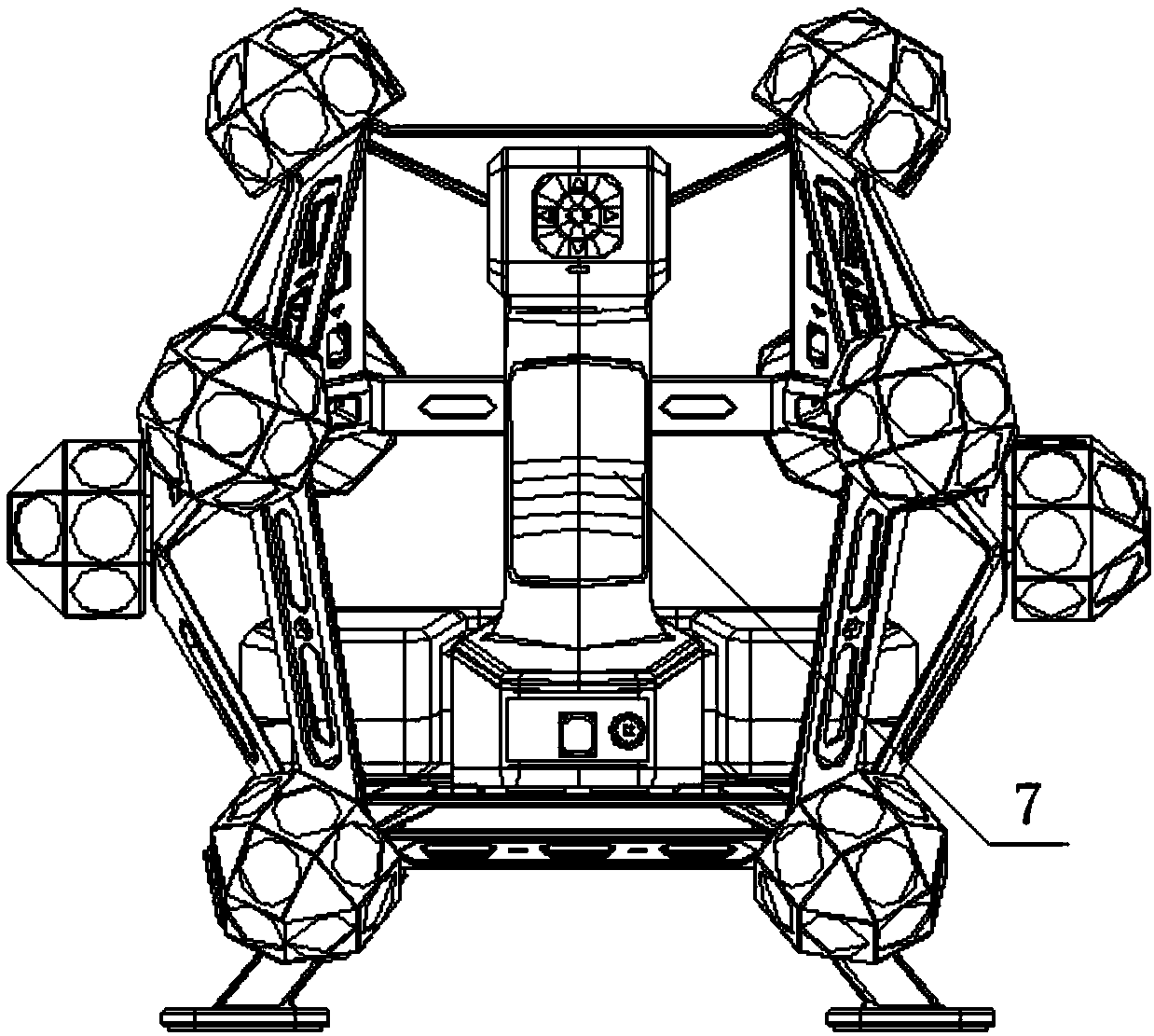
[0040] Such as Figure 1 to Figure 8 As shown, a spherical scanner includes a hollow polyhedron-shaped main body 1, a plurality of target balls 2, two cameras 3 and a scanner 4, and a plurality of target balls 2 are arranged on the vertices of the main body 1 in one-to-one correspondence position, the surface of the target ball 2 is provided with a plurality of mark reflective points, the two cameras 3 and the scanner 4 are all arranged in the main body 1, and the two cameras 3 and the scanner 4 are connected with the The main body 1 is connected, and the lenses of the two cameras 3 and the emitting ends of the scanner 4 are set towards the same side of the main body 1 .

[0041] In the present invention, through t...


PUM


Abstract

The invention relates to a spherical scanner and a three-dimensional scanning system. The spherical scanner comprises a hollow-out main body, a plurality of target balls, two cameras and a scanning unit. The plurality of target balls are arranged at vertexes of the main body in a one-to-one correspondence manner. A plurality of mark reflection points are arranged on the surfaces of the target balls. The two cameras and the scanning unit are arranged inside the main body and are connected with the main body; and lenses of the two cameras and the emitting end of the scanning unit are arranged toface the same side of the main body. According to the invention, on the basis of cooperation of the scanning unit and the cameras, modeling of a target object surface is carried out in real time; with the multiple target balls arranged on the main body, a tracking device is able to identify the mark reflection points arranged on the surfaces of the target balls that are not shielded within a viewfield range during the tracking process; and modeling of the surface of the target object is carried out by the scanning unit and the cameras, so that accurate three-dimensional scanning is realized.Moreover, the spherical scanner has advantages of simple structure, small size and beautiful appearance; and the working space can be extended.

Description

technical field [0001] The invention relates to the technical field of optical scanning, in particular to a sphere scanner and a three-dimensional scanning system. Background technique [0002] 3D laser scanners have been able to conveniently solve most of the high-precision measurement tasks that do not require the surface texture of objects, but they must paste a certain number of evenly distributed reflective marker points on the surface of the object to be measured for frame splicing during scanning, while pasting reflective The process of marking points is cumbersome and takes a lot of time, which increases the workload of scanning and measurement. It is also not suitable for high-value items such as high-precision equipment and cultural relics that do not allow marking points to be pasted on the surface. [0003] The white light scanner in the prior art does not need to stick marker points on the surface of the object to be measured for image positioning and posture de...

Claims


Application Information

Patent Timeline
Patent Type & Authority Applications(China)
IPC IPC(8): G01B11/00
CPCG01B11/002
Inventor 郑顺义王晓南成剑华刘庆龙朱锋博
Owner ZG TECH CO LTD
Why Eureka
Try Eureka