
Microchannel heat sink having special shunting structure

A technology of microchannels and flow channels, which is applied in cooling/ventilation/heating transformation, electrical equipment structural parts, electrical components, etc., can solve the problem of uneven flow distribution, achieve the effect of improving heat transfer uniformity and comprehensive ability

Active Publication Date: 2018-09-28
SICHUAN UNIV
View PDF5 Cites 6 Cited by
  • Summary
  • Abstract
  • Description
  • Claims
  • Application Information

AI Technical Summary

Problems solved by technology

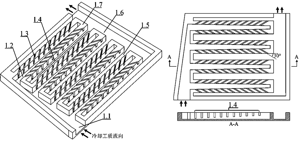
The cooling working fluid first flows into the heat sink from the main inflow channel (1.1), and then divides the flow from the main inflow channel (1.1) to each sub-channel (1.2) for the first time. Excessive flow is distributed to the downstream, so that the flow distributed by each sub-channel is relatively uniform, and the problem of relatively serious uneven flow distribution inside the general split heat sink is overcome

Method used


Image

  • Microchannel heat sink having special shunting structure
  • Microchannel heat sink having special shunting structure
  • Microchannel heat sink having special shunting structure

Examples


Embodiment Construction

[0019] The main content of the present invention is further illustrated below in conjunction with specific embodiments, but the content of the present invention is not limited to the following embodiments.

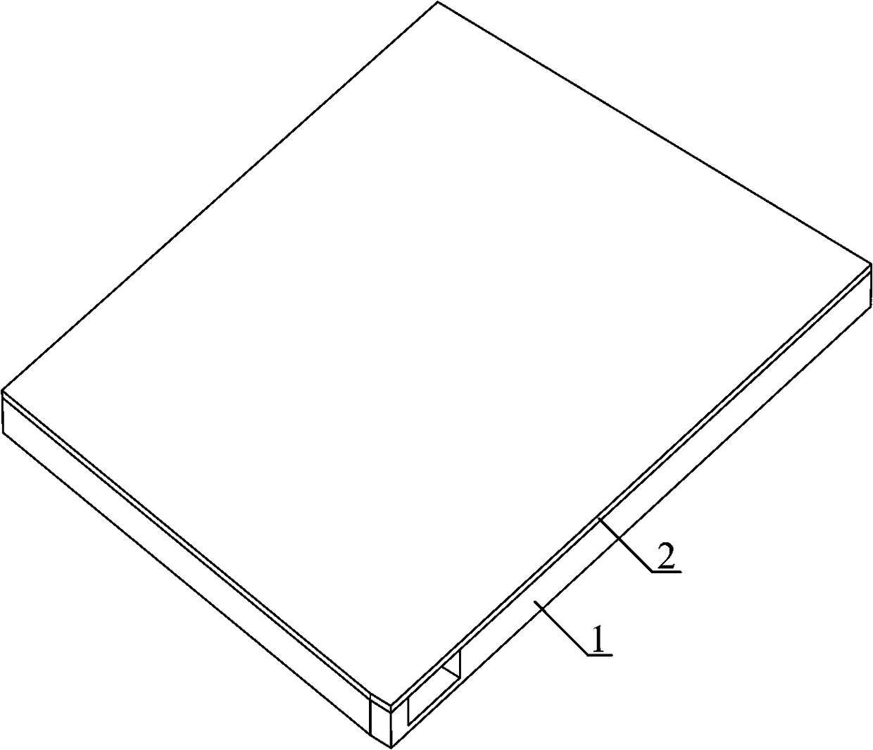
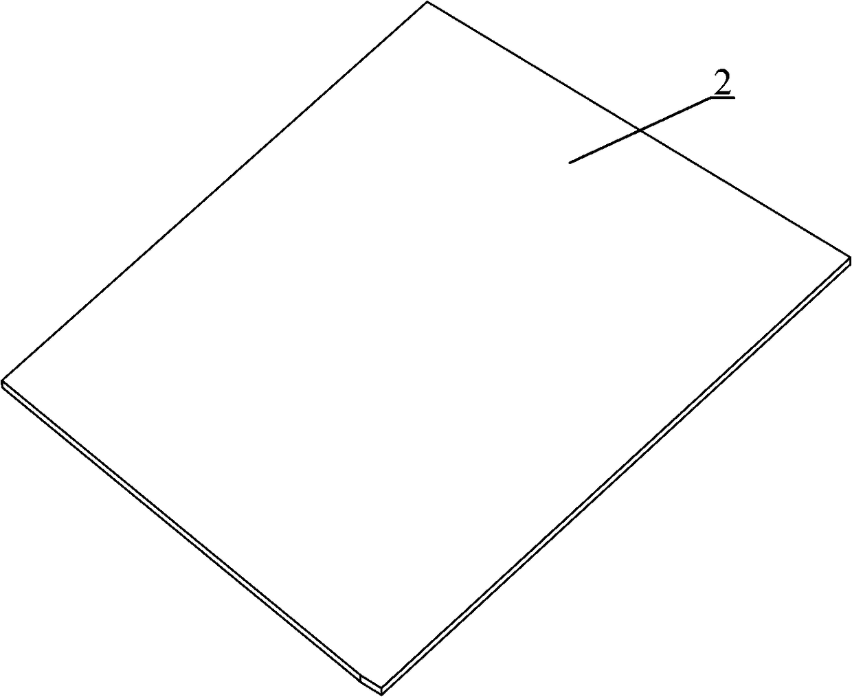
[0020] The invention discloses a microchannel heat sink with a special shunt structure, which comprises a shunt module and a soaking bottom plate directly contacting with a heat releasing device above it. The shunt module includes the main inflow channel (1.1), the shunt sub-channel (1.2), the overflow channel (1.3), the outflow sub-channel (1.5), and the main outflow channel (1.6). The main inlet channel (1.1) has a slope. The two side walls of the shunt sub-channel (1.2) are inclined toward the center to form a tapered channel structure. The overflow channel (1.3) is arranged obliquely; along the direction of the main flow in the inflow branch, the overflow channel (1.3) is highly non-linearly reduced (1.4).

[0021] In this embodiment, the main inflow channel (1.1) has a r...


PUM


Abstract

The invention discloses a microchannel heat sink having the special shunting structure. The heat sink comprises a shunting module and a uniform heating base plate which is arranged above the shuntingmodule and directly contacts with heat release equipment, wherein the shunting module comprises a main in-flow channel, a shunting sub channel, an overflow channel, an out-flow sub channel and a mainout-flow channel, the cooling working medium enters the heat sink from the main in-flow channel, the main in-flow channel employs the cross section tapered structure, the cooling working medium is guaranteed to distribute to each shunting sub channel, the overflow channel is formed through directly processing on a solid wall surface of the shunting sub channel, through inclination arrangement, theoverflow channel and the shunting sub channel are made to form a relatively small incident flow angle, so flow resistance is reduced. Along the main flow direction in the shunting sub channel, heightof the overflow channel is gradually reduced, the cross section tapered structure is employed at the shunting sub channel, the excessive cooling work medium can be prevented from flowing to the downstream overflow channel of the sub channels, flow distribution in the whole heat sink is made to be uniform, and heat exchange uniformity of the heat sink is guaranteed. The method is advantaged in that through the special shunting structure and the overflow channel structure, the distribution process in the heat sink is made to be uniform, and integral heat exchange efficiency and heat exchange uniformity of the heat sink are improved.

Description

Technical field [0001] The invention relates to a heat sink suitable for cooling systems of high-heating, compact equipment, such as high-performance electronic chips, high-power laser diodes, concentrating solar cells, etc., and is a microchannel heat sink with a special shunt structure . Background technique [0002] Many miniaturized, high-heating devices, such as high-performance electronic chips, high-power laser diodes, concentrating solar cells, etc., will produce strong heat release during operation (even exceeding 100W / cm 2 ), effective cooling has become an important prerequisite for the reliable operation of these equipment, and related technologies have always been research hotspots. [0003] Compared with traditional air-cooled heat sinks, liquid-cooled micro-channel heat sinks have stronger heat exchange capacity and are more suitable for cooling high heat-releasing equipment. It is the main development direction of cooling technology for high-heat electronic equipmen...

Claims


Application Information

Patent Timeline
Patent Type & Authority Applications(China)
IPC IPC(8): H05K7/20
CPCH05K7/20272H05K7/20281
Inventor 唐巍孙立成杜敏唐继国刘洪涛谢果莫政宇鲍静静
Owner SICHUAN UNIV
Learn More