
Broadband circularly polarized UHF RFID reader antenna with easy-to-match impedance

An impedance matching and circular polarization technology, applied in the field of UHFRFID reader antenna, can solve the problems of complex optimization process, increase of antenna structure and volume, and high correlation of antenna input impedance, and achieve simple optimization steps and good input reactance matching. , the effect of covering a wide frequency band

Inactive Publication Date: 2018-09-28
CHONGQING UNIV OF POSTS & TELECOMM
View PDF5 Cites 8 Cited by
  • Summary
  • Abstract
  • Description
  • Claims
  • Application Information

AI Technical Summary

Problems solved by technology

Some of the existing UHF RFID wide-bandwidth circularly polarized antennas use E-shaped, U-shaped and L-shaped slot structures to achieve wide bandwidth coverage of circular polarization. However, the input impedance of the antenna has a large correlation with circularly polarized radiation. Does not have the advantages of independent optimization of circular polarization and impedance matching, and the optimization process is complicated
Some UHF RFID wide-bandwidth circularly polarized antennas expand the circularly polarized bandwidth by adding parasitic radiation patches. However, in order to achieve good impedance matching, an additional impedance matching layer is added, which increases the structure and volume of the antenna.

Method used


Image

  • Broadband circularly polarized UHF RFID reader antenna with easy-to-match impedance
  • Broadband circularly polarized UHF RFID reader antenna with easy-to-match impedance
  • Broadband circularly polarized UHF RFID reader antenna with easy-to-match impedance

Examples


Embodiment Construction

[0025] The present invention will be further described below with reference to the accompanying drawings and examples. It should be noted that this embodiment is based on the technical solution, but the scope of protection of the present invention is not limited to this embodiment.

[0026] like figure 1 As shown, the broadband circularly polarized UHF RFID reader antenna with easy impedance matching mainly includes ground metal patch 1 parallel to each other, air dielectric layer 2.1, FR-4 dielectric substrate 3, main radiation patch 4, Air dielectric layer 2.2, parasitic radiation patch 5.

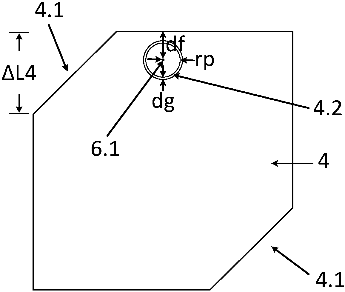
[0027] like figure 1 , 2 As shown, the antenna is fed by a coaxial feed probe 6, and the feed point 6.1 is as figure 2 shown.

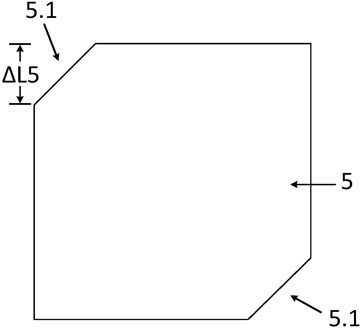
[0028] like figure 1 , 2 , 3, the main radiation patch 4 and the parasitic radiation patch 5 have equilateral triangular cut corners 4.1 and 5.1 respectively, by optimizing the sizes ΔL4 and ΔL5 of the cut corners 4.1 and 5.1, and the thickness h of the a...


PUM

PropertyMeasurementUnit
Thicknessaaaaaaaaaa
Thicknessaaaaaaaaaa

Abstract

The invention discloses a broadband circularly polarized UHF RFID reader antenna with easy-to-match impedance. The antenna is characterized by comprising a grounding plate, an air dielectric layer 1,an FR-4 dielectric substrate, a main radiation patch, an air dielectric layer 2, a parasitic radiation patch and a coaxial feed probe from bottom to top, wherein the grounding plate, the air dielectric layer 1, the FR-4 dielectric substrate, the main radiation patch, the air dielectric layer 2 and the parasitic radiation patch are parallel; the coaxial feed probe vertically feeds the main radiation patch through the grounding plate; the main radiation patch and the parasitic radiation patch are square after equilateral chamfering at opposite angles; the main radiation patch comprises an annular gap impedance matching unit; distances from the annular gap impedance matching unit to left and right sides of the main radiation patch are equal; an inner circle center of the annular gap impedancematching unit is a coaxial feed probe feed point. The broadband circularly polarized UHF RFID reader antenna with the easy-to-match impedance can realize left-hand circular polarization and good impedance matching in 860-940 MHz frequency band, and has the advantages of being circularly polarized and realizing independent input impedance matching.

Description

technical field [0001] The invention relates to the technical field of UHF RFID reader-writer antennas, in particular to a broadband circularly polarized UHF RFID reader-writer antenna with easy impedance matching. Background technique [0002] The reader antenna is an important part of the UHF RFID system. The realization of its circular polarization can effectively improve the distance of the system to identify passive and linearly polarized tags, meet the low-cost requirements of UHF RFID, and promote the large-scale commercial use of UHF RFID. According to the UHF RFID frequency band division of major countries and regions in the world, it can be known that UHF RFID includes two important frequency bands (860-870MHz) and (902-928MHz). If the UHF RFID reader antenna only achieves circular polarization coverage in the (902-928MHz) or (860-870MHz) frequency bands, and does not cover two important UHF RFID frequency bands at the same time, it cannot be used in most countries...

Claims


Application Information

Patent Timeline
IPC IPC(8): H01Q1/38H01Q1/48H01Q1/50H01Q5/20H01Q5/307H01Q1/22
Inventor 罗志勇赵洪图沈勋任仪马国喜张雪杨美美韩弘祖
Owner CHONGQING UNIV OF POSTS & TELECOMM
Learn More