
LCD panel fan-out area and LCD panel

A technology of liquid crystal panel and fan-out area, applied in instruments, nonlinear optics, optics, etc., can solve the problems of tight wiring space, close spacing between pins, abnormal panel display, etc.

Active Publication Date: 2020-11-24
TCL CHINA STAR OPTOELECTRONICS TECH CO LTD
View PDF13 Cites 0 Cited by
  • Summary
  • Abstract
  • Description
  • Claims
  • Application Information

AI Technical Summary

Problems solved by technology

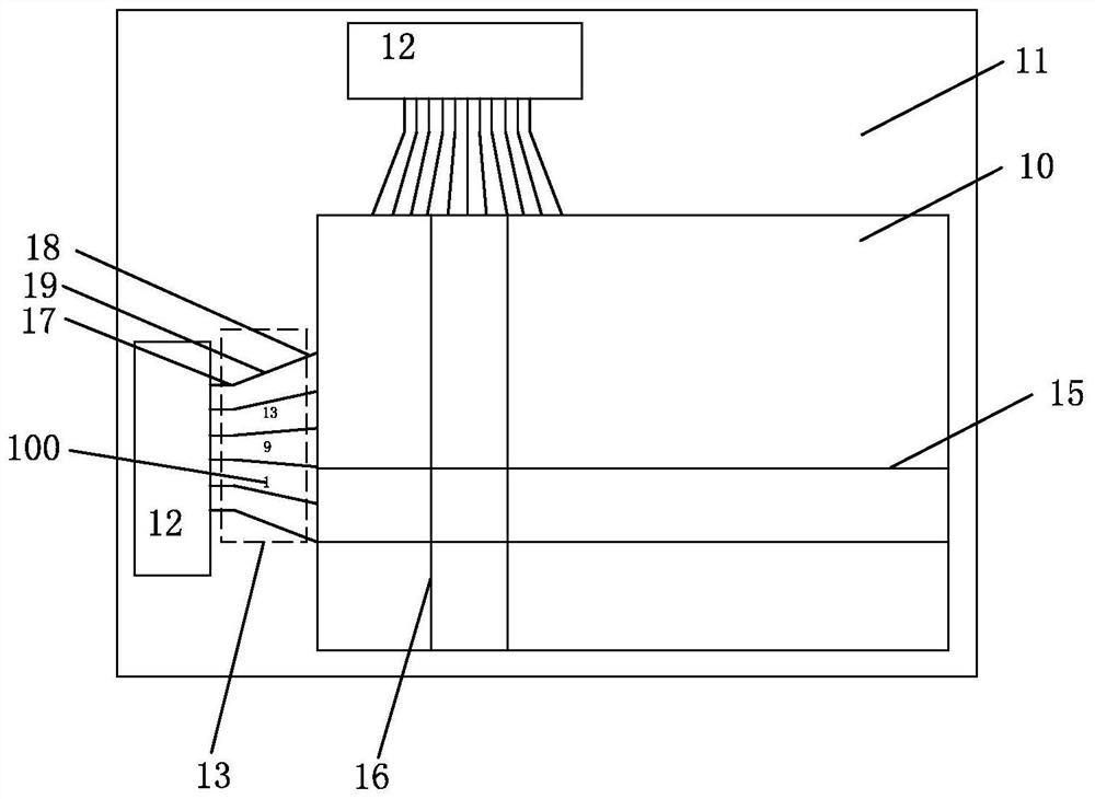
However, when using 1440pin, there will also be certain problems. The increase in the number of pins will also lead to tight wiring space, reduced pin width, and closer spacing between pins.
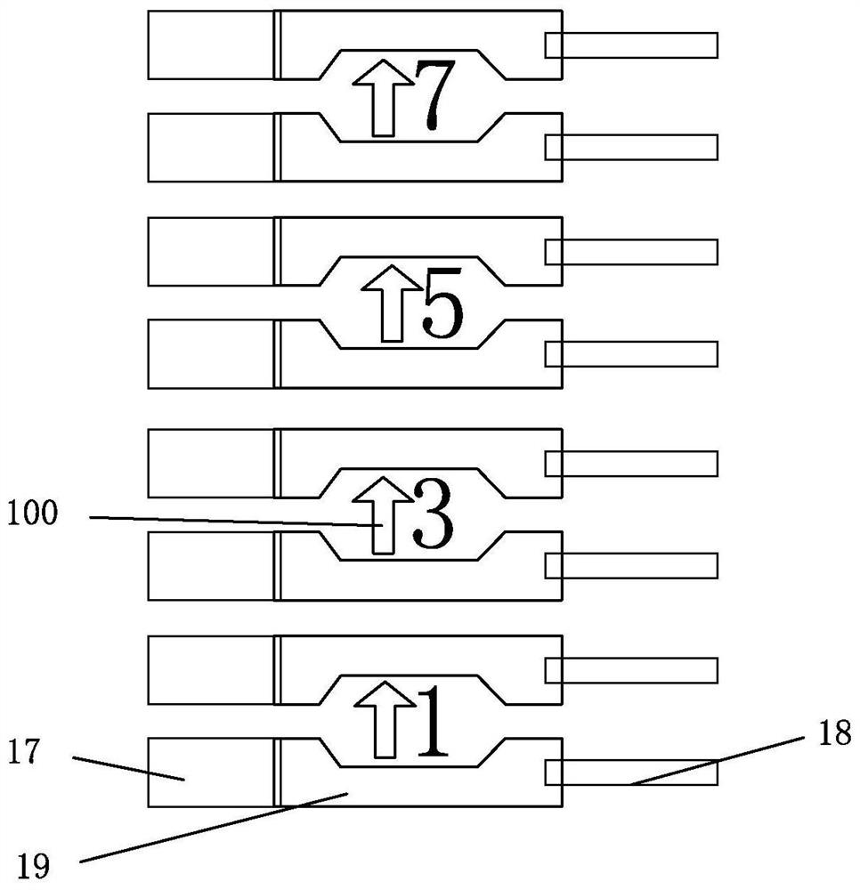
At this point if using figure 2 The logo design method is very prone to short circuit (short) phenomenon between the pin wiring and the middle digital logo, resulting in abnormal display of the panel, failure to light up normally, and loss

Method used


Image

  • LCD panel fan-out area and LCD panel
  • LCD panel fan-out area and LCD panel
  • LCD panel fan-out area and LCD panel

Examples


Embodiment Construction

[0029] In order to further illustrate the technical means adopted by the present invention and its effects, the following describes in detail in conjunction with preferred embodiments of the present invention and accompanying drawings.

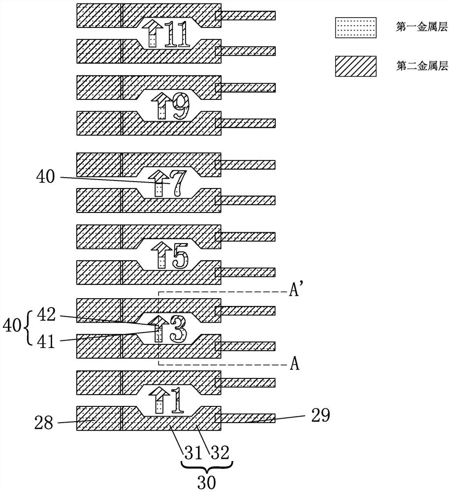
[0030] see Figure 3 to Figure 7 , the present invention provides a fan-out area of ​​a liquid crystal panel, including a plurality of pin routings 28, a plurality of fan-out routings 29, and a wire for connecting the plurality of pin routings 28 and the plurality of fan-out routings 29 A plurality of connection lines 30, and a plurality of identification patterns 40 for identifying the plurality of connection lines 30; each connection line 30 includes a first wire 31 formed by a first metal layer and a first wire 31 formed by a second metal layer Two wires 32; each of the identification patterns 40 includes a first portion 41 and a second portion 42 that are insulated from each other.

[0031] Specifically, a plurality of connection lines 30...


PUM


Abstract

The invention provides an LCD (liquid crystal display) panel fanout area and an LCD panel. The LCD panel fanout area comprises multiple pin lines, multiple fanout lines, multiple connecting lines usedfor connecting the multiple pin lines and the multiple fanout lines as well as multiple logo patterns used for marking the multiple connecting lines, wherein each connecting line comprises a first guide wire formed by a first metal layer and a second guide wire formed by a second metal layer; each logo pattern comprises a first part and a second part which are mutually insulated. Even if short circuiting occurs between the first part and / or the second part of each logo pattern and the corresponding connecting line, short circuiting between two adjacent connecting lines cannot be caused, so that the logo patterns can be effectively formed through exposure when the distance between the connecting lines is reduced, the distance between two adjacent connecting lines can be set to be smaller,and a driver chip with a larger number of pins is conveniently used.

Description

technical field [0001] The invention relates to the field of display technology, in particular to a liquid crystal panel fan-out area and a liquid crystal panel. Background technique [0002] A liquid crystal display (Liquid Crystal Display, LCD) has many advantages such as a thin body, power saving, and no radiation, and has been widely used. Such as: LCD TV, mobile phone, personal digital assistant (PDA), digital camera, computer screen or laptop screen, etc. [0003] The structure of the liquid crystal panel is composed of a color filter (Color Filter, CF) substrate, a thin film transistor array (Thin Film Transistor Array, TFT Array) substrate and a liquid crystal layer (Liquid Crystal Layer) arranged between the two substrates. Its working principle is to control the rotation of the liquid crystal molecules in the liquid crystal layer by applying a driving voltage on the two glass substrates, and refract the light from the backlight module to produce a picture. [000...

Claims


Application Information

Patent Timeline
Patent Type & Authority Patents(China)
IPC IPC(8): G02F1/1345
CPCG02F1/13452
Inventor 安立扬
Owner TCL CHINA STAR OPTOELECTRONICS TECH CO LTD
Learn More