
Fault diagnosing and health monitoring device on basis of piezoelectric vibration energy collection

A technology of energy collection and fault diagnosis, which is applied in the direction of measuring devices, electric devices, piezoelectric effect/electrostrictive or magnetostrictive motors, etc., which can solve the impact of machining accuracy, vibration frequency change, severe vibration of equipment and even disintegration and other issues, to achieve the effect of flexible structure, avoiding losses, and strong practicability

Inactive Publication Date: 2018-09-28
HARBIN ENG UNIV
View PDF12 Cites 2 Cited by
  • Summary
  • Abstract
  • Description
  • Claims
  • Application Information

AI Technical Summary

Problems solved by technology

[0002] In industrial production, the equipment needs to run smoothly. When some key parts of the equipment are loose or some components are damaged, the equipment may vibrate violently or even disintegrate. When the equipment fails, the vibration frequency will change and affect the machining accuracy. It even poses a threat to the life of production workers

Method used


Image

  • Fault diagnosing and health monitoring device on basis of piezoelectric vibration energy collection
  • Fault diagnosing and health monitoring device on basis of piezoelectric vibration energy collection
  • Fault diagnosing and health monitoring device on basis of piezoelectric vibration energy collection

Examples


Embodiment Construction

[0021] The present invention will be described in further detail below with reference to the accompanying drawings and specific embodiments.

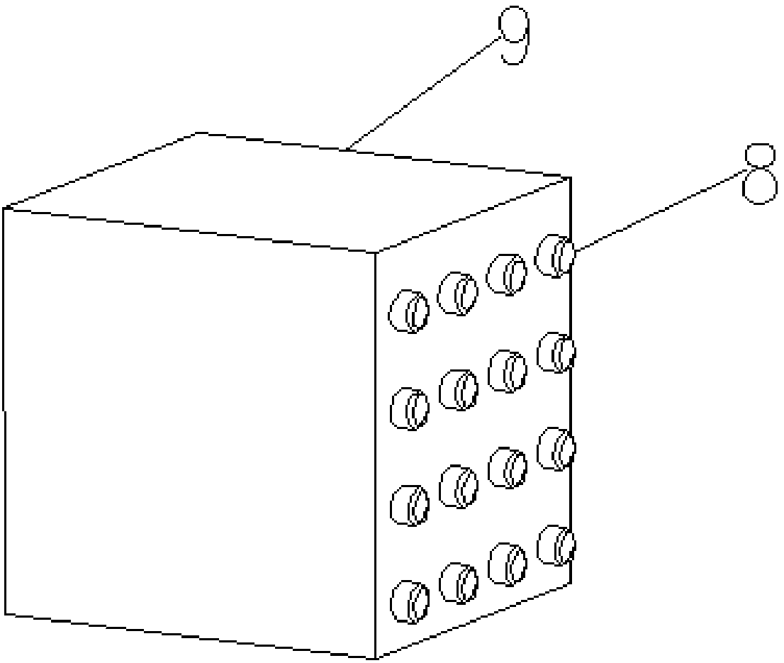
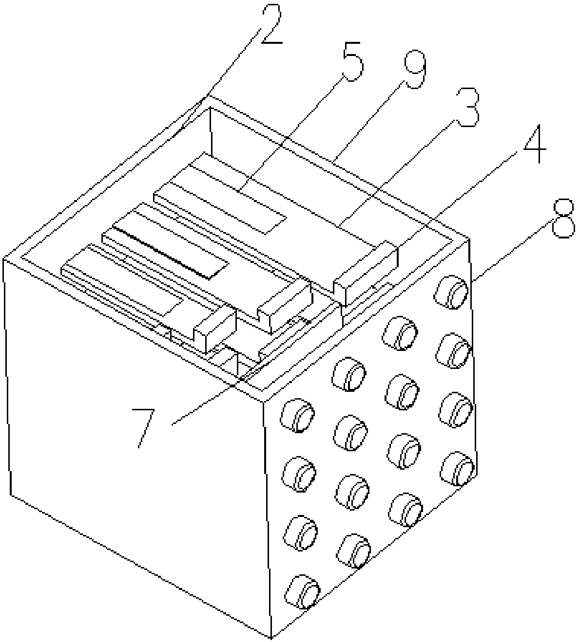
[0022] The present invention includes a frequency collector 1 , a circuit conversion part 7 , and an LED status indicator 8 . The frequency collector 1 is connected to the circuit conversion part 7 through a wire, and the circuit conversion part 7 converts the electric energy into the corresponding LED status indicator 9 to provide electric energy, and judges the vibration of the monitored equipment by observing the on and off of the LED status indicator 8 frequency.

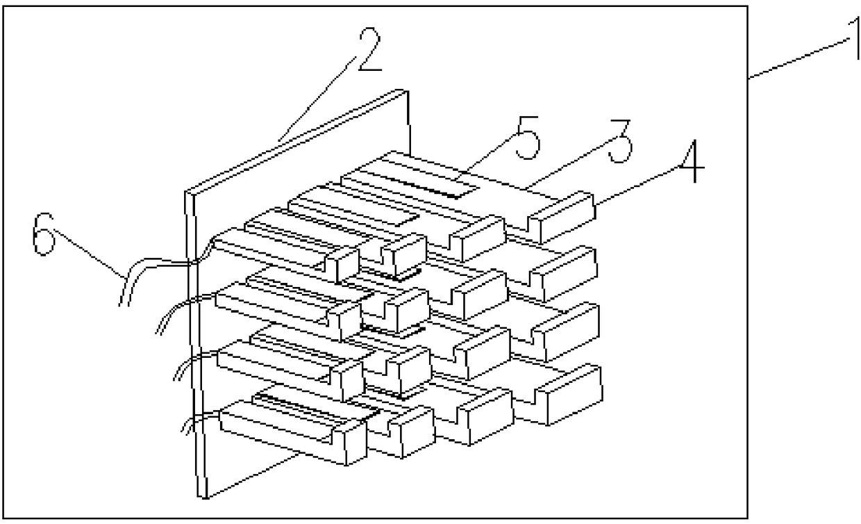
[0023] The frequency collector 1 includes a cantilever beam fixed vertical plate 2 and a cantilever beam array 3 on the same vertical plate, and each cantilever beam is numbered. The width, thickness and length of each cantilever beam structure in the cantilever beam array 2 are different. The PVDF piezoelectric power generation material 5 is pasted on the surface of the...


PUM


Abstract

The invention provides a fault diagnosing and health monitoring device on the basis of piezoelectric vibration energy collection. The fault diagnosing and health monitoring device comprises a box, a frequency acquisition apparatus, a circuit switching portion and an indicator lamp array. The frequency acquisition apparatus and the circuit switching portion are arranged in the box, the indicator lamp array is arranged on a surface of the box, the frequency acquisition apparatus comprises a cantilever beam fixing plate, a cantilever beam array, cantilever beam balancing weights and PVDF (polyvinylidene fluoride) piezoelectric materials, the cantilever beam fixing plate is arranged on the inner surface of the box, the cantilever beam array is arranged on the cantilever beam fixing plate, thecorresponding cantilever beam balancing weight is arranged at a free end of each cantilever beam of the cantilever beam array, the corresponding PVDF piezoelectric materials are arranged on the uppersurface of each cantilever beam of the cantilever beam array, PVDF piezoelectric material electrodes are further connected with the upper surfaces and the lower surfaces of the PVDF piezoelectric materials, the circuit switching portion is arranged in the inner middle of the box and is connected with the PVDF piezoelectric material electrodes and corresponding indicator lamps, and the number of the indicator lamps corresponds to that of the cantilever beams. The fault diagnosing and health monitoring device has the advantages of simple structure, small volume, low energy consumption and manufacturing cost, zero pollution and low service life.

Description

technical field [0001] The invention relates to a fault diagnosis and health monitoring device based on piezoelectric vibration energy collection, belonging to the field of health monitoring of equipment in industrial production. Background technique [0002] In industrial production, the equipment needs to run smoothly. When some key components of the equipment are loose, or some components are damaged, the equipment may vibrate violently or even disintegrate. When the equipment fails, the vibration frequency will change and affect the machining accuracy. Even life-threatening to production workers. When equipment is abnormal, if it can be found as soon as possible, losses can be reduced. Therefore, the health monitoring of equipment is particularly important. [0003] Sensors are mostly used in alarms. The application of sensors can convert the information to be measured into electrical signals or other forms of signals that can be measured to monitor the normal operatio...

Claims


Application Information

Patent Timeline
Patent Type & Authority Applications(China)
IPC IPC(8): G01H11/08H02N2/18
CPCG01H11/08H02N2/186
Inventor 王威远王晓波薛开和修明黄文浩
Owner HARBIN ENG UNIV
Learn More