An automatic control valve for turning plow

A technology for automatic control of valves and turning plows, applied in the field of valves, can solve problems such as high cost, poor reliability, and complex structure, and achieve the effects of low manufacturing cost, compact size, and high degree of automation

Active Publication Date: 2020-08-11
SHANGHAI JIANGLANG TECH CO LTD
View PDF7 Cites 0 Cited by
  • Summary
  • Abstract
  • Description
  • Claims
  • Application Information

AI Technical Summary

Problems solved by technology

However, the structure is very complicated, the reliability is poor, and the cost of two control rotary valves is still high

Method used


Image

  • An automatic control valve for turning plow
  • An automatic control valve for turning plow
  • An automatic control valve for turning plow

Examples


Embodiment Construction

[0018] The present invention will be further described in detail below in conjunction with the accompanying drawings and embodiments.

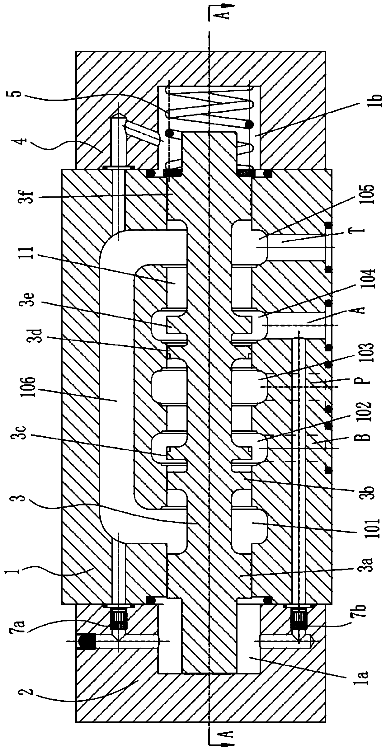
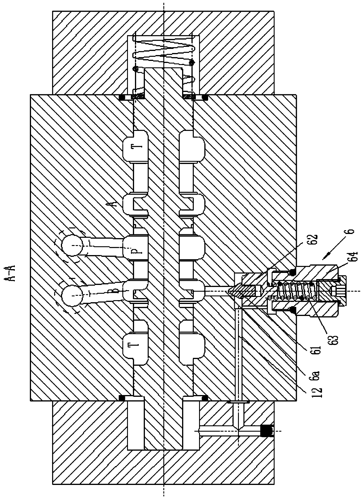
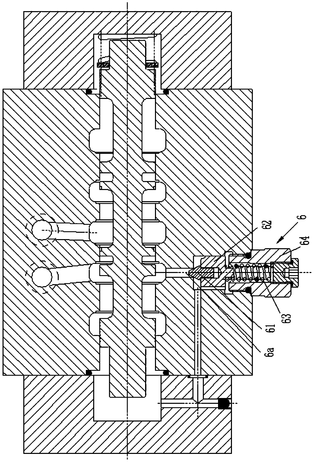
[0019] Such as Figure 1~3 Shown is a preferred embodiment of the present invention.

[0020] An automatic control valve for turning a plow comprising:

[0021] Valve block 1, valve block 1 is provided with oil inlet P, oil return port T, first working oil port A and second working oil port B;

[0022] The first passage 11, the first passage 11 has annular first flow groove 101, second flow groove 102, third flow groove 103, fourth flow groove 104 and fifth flow groove 105, valve block 1 is also provided with a first flow channel 106 for connecting the first flow groove 101 and the fifth flow groove 105, the second flow groove 102 is connected with the second working oil port B, and the third flow groove 103 is connected with the inlet port B. The oil port P is connected, the fourth flow groove 104 is connected with the first working oil po...


PUM


Abstract

The invention relates to an automatic control valve for a turnover plow. The automatic control valve for the turnover plow is characterized by comprising a valve block, a first channel, a second channel and an overflow valve; an oil inlet, an oil returning port, a first working oil port and a second working oil port are formed in the valve block; a reversing valve core is arranged in the first channel; a primary control cavity is formed in the first channel on one side of the reversing valve core; a secondary control cavity is formed in the first channel on the other side of the reversing valve core; the second channel is used for communicating the second working oil port and the secondary control cavity; the overflow valve is arranged on the second channel for normally disconnecting the second channel; and when the pressure of the second working oil port reaches a certain valve, the overflow valve is open, and oil flows into the primary control cavity from the second working oil port.The automatic control valve for the turnover plow is simple and reasonable in structure and low in cost, and can automatically control the turnover plow to overturn.

Description

technical field [0001] The invention belongs to the technical field of valves, in particular to an automatic control valve for turning plows. Background technique [0002] In recent years, most areas of my country have begun to promote the application of hydraulic turning plows. Using the reversing plow for plowing has the advantages of no opening and closing ridges, high production efficiency, and energy saving. The hydraulic reversing plow uses the hydraulic system of the tractor to control the left and right plow bodies to operate alternately, so as to achieve the purpose of no opening and closing ridges. Such as Figure 6 As shown, the turning mechanism of the hydraulic turning plow mainly includes a suspension frame 111, a rotating shaft 115, a plow beam 112 and an oil cylinder 113. The rotating shaft 115 is welded on the suspension frame 111, and the plow beam 112 is installed on the rotating shaft 115. Respectively hinged on the suspension frame top and the plow bea...

Claims


Application Information

Patent Timeline
Patent Type & Authority Patents(China)
IPC IPC(8): F15B13/042F16K11/07A01B15/00
CPCA01B15/00F15B13/0402F15B2013/041F16K11/07
Inventor 邵立坤
Owner SHANGHAI JIANGLANG TECH CO LTD
Why Eureka
Try Eureka