A kind of oil switching valve

An oil circuit switching and reversing valve technology, applied in the field of hydraulic valves, can solve the problems of poor reliability, complex structure and high cost, and achieve the effects of low cost, high degree of automation and simple structure

Active Publication Date: 2020-07-14
淮安市君宝液压机械有限公司
View PDF6 Cites 0 Cited by
  • Summary
  • Abstract
  • Description
  • Claims
  • Application Information

AI Technical Summary

Problems solved by technology

However, the structure is very complicated, the reliability is poor, and the cost of two control rotary valves is still high

Method used


Image

  • A kind of oil switching valve
  • A kind of oil switching valve
  • A kind of oil switching valve

Examples


Embodiment Construction

[0021] The present invention will be further described in detail below in conjunction with the accompanying drawings and embodiments.

[0022] Such as Figure 1~2 Shown is a preferred embodiment of the present invention.

[0023] An oil circuit switching valve, comprising:

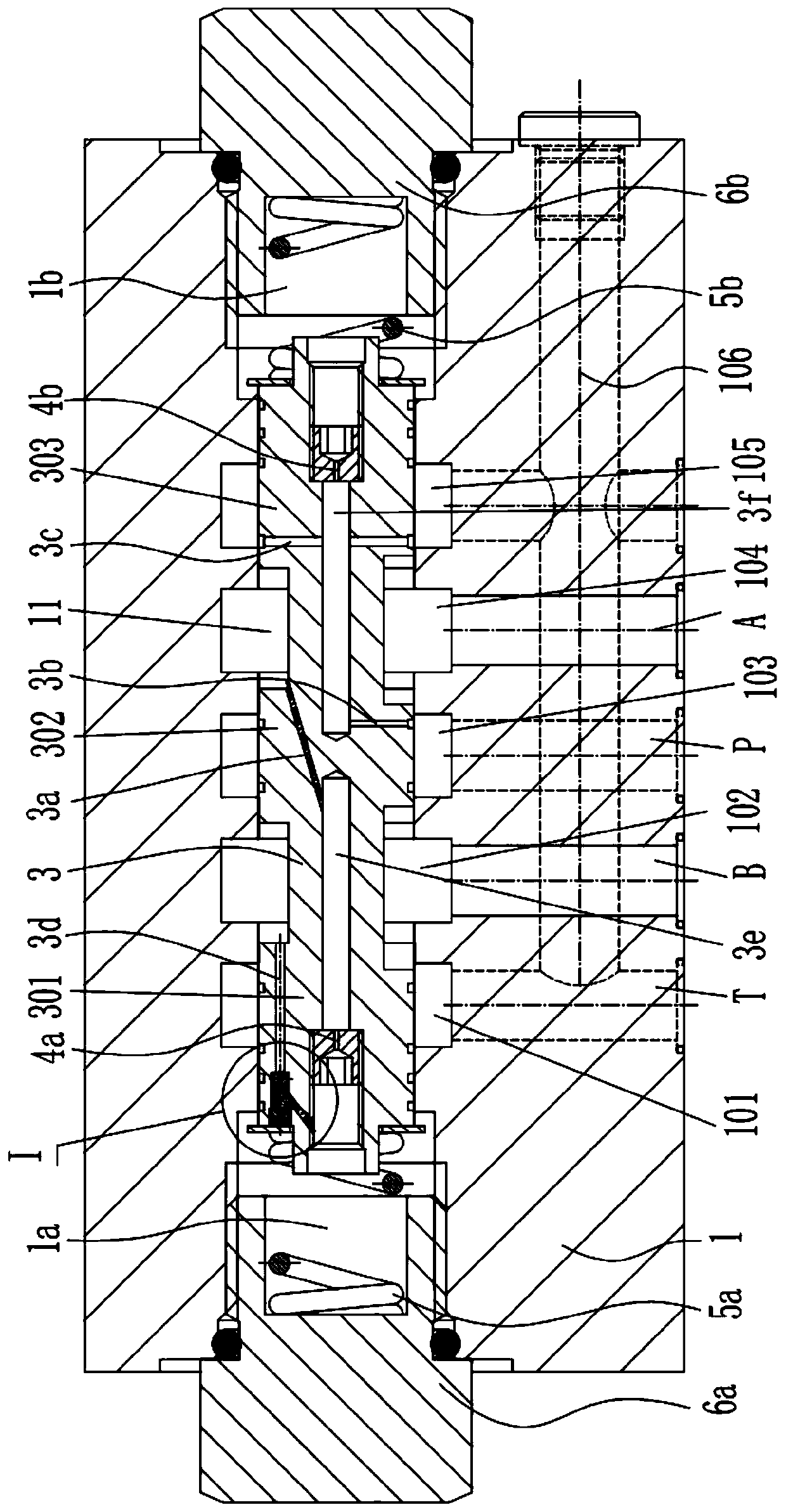
[0024] Valve block 1, the valve block 1 is provided with an oil inlet P, an oil return port T, a first working oil port A and a second working oil port B, and the valve block 1 is provided with a first passage 11 axially penetrating through, and the second A channel 11 has annular first flow groove 101, second flow groove 102, third flow groove 103, fourth flow groove 104 and fifth flow groove 105, the first flow groove 101 and the return The oil port T is connected, the second flow groove 102 is connected with the second working oil port B, the third flow groove 103 is connected with the oil inlet P, and the fourth flow groove 104 is connected with the first working oil port A The fifth flow groove 105...


PUM


Abstract

The invention relates to an oil channel switchover valve. The oil channel switchover valve is characterized by comprising a valve block, a reversing valve element, a first screw plug, a second screw plug, a first spring, a second spring and an overflow valve, wherein an oil inlet port, an oil return port, a first working oil port and a second working oil port are formed in the valve block; a firstchannel is formed in the valve block; the reversing valve element is slidably arranged in the first channel; the first screw plug and the second screw plug are fixed to the left end and the right endof the valve block separately and used for plugging the first channel; the first spring is arranged in a primary control cavity; the second spring is arranged in a secondary control cavity; the overflow valve is arranged on a first flow channel and used for normally cutting off the first flow channel; and the reversing valve element can be switched over among a first position, a second position and a third position. The oil channel switchover valve is simple in structure, low in manufacturing cost, and capable of realizing automatic control.

Description

technical field [0001] The invention belongs to the technical field of hydraulic valves, in particular to an oil circuit switching valve. Background technique [0002] In recent years, most areas of my country have begun to promote the application of hydraulic turning plows. Using the reversing plow for plowing has the advantages of no opening and closing ridges, high production efficiency, and energy saving. The hydraulic reversing plow uses the hydraulic system of the tractor to control the left and right plow bodies to operate alternately, so as to achieve the purpose of no opening and closing ridges. Such as Figure 7 As shown, the turning mechanism of the hydraulic turning plow mainly includes a suspension frame 111, a rotating shaft 115, a plow beam 112 and an oil cylinder 113. The rotating shaft 115 is welded on the suspension frame 111, and the plow beam 112 is installed on the rotating shaft 115. Respectively hinged on the suspension frame top and the plow beam 11...

Claims


Application Information

Patent Timeline
Patent Type & Authority Patents(China)
IPC IPC(8): F15B13/02
CPCF15B13/021
Inventor 邵立坤
Owner 淮安市君宝液压机械有限公司
Why Eureka
Try Eureka