Feeding device in wire welding machine

A feeding device and welding wire technology, which is applied in the field of auxiliary equipment for flux-cored welding wire production, can solve the problems of uncontrollable powder discharge in the hopper, waste, and high production costs, and achieve convenient control and adjustment, reduce waste, and reduce production costs Effect

Pending Publication Date: 2018-09-28
JIANGSU XINZHOU WEAR-RESISTANT TECH CO LTD
View PDF6 Cites 2 Cited by
  • Summary
  • Abstract
  • Description
  • Claims
  • Application Information

AI Technical Summary

Problems solved by technology

The disadvantages of the above-mentioned feeding device are: (1) it is impossible to control the amount of powder discharged in the hopper; (2) the powder is easily scattered outside the conveyor belt during the process of feeding to the conveyor belt, resulting in waste, and the production cost of the enterprise high

Method used


Image

  • Feeding device in wire welding machine
  • Feeding device in wire welding machine
  • Feeding device in wire welding machine

Examples


Embodiment Construction

[0015] The present invention will be further described below in conjunction with the accompanying drawings and specific embodiments.

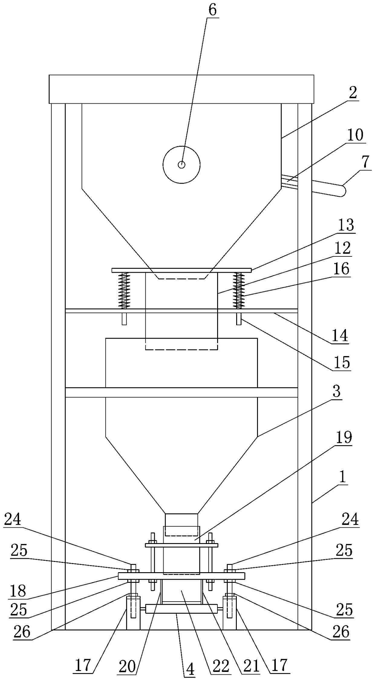
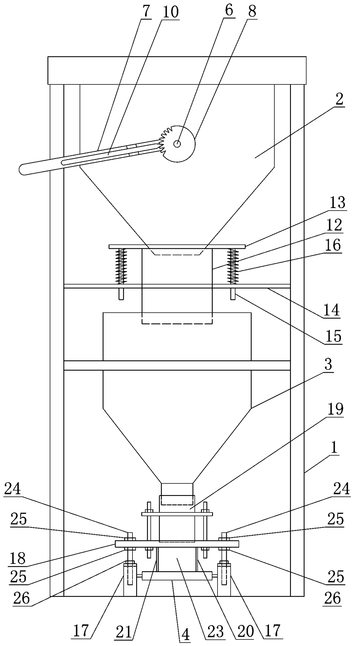
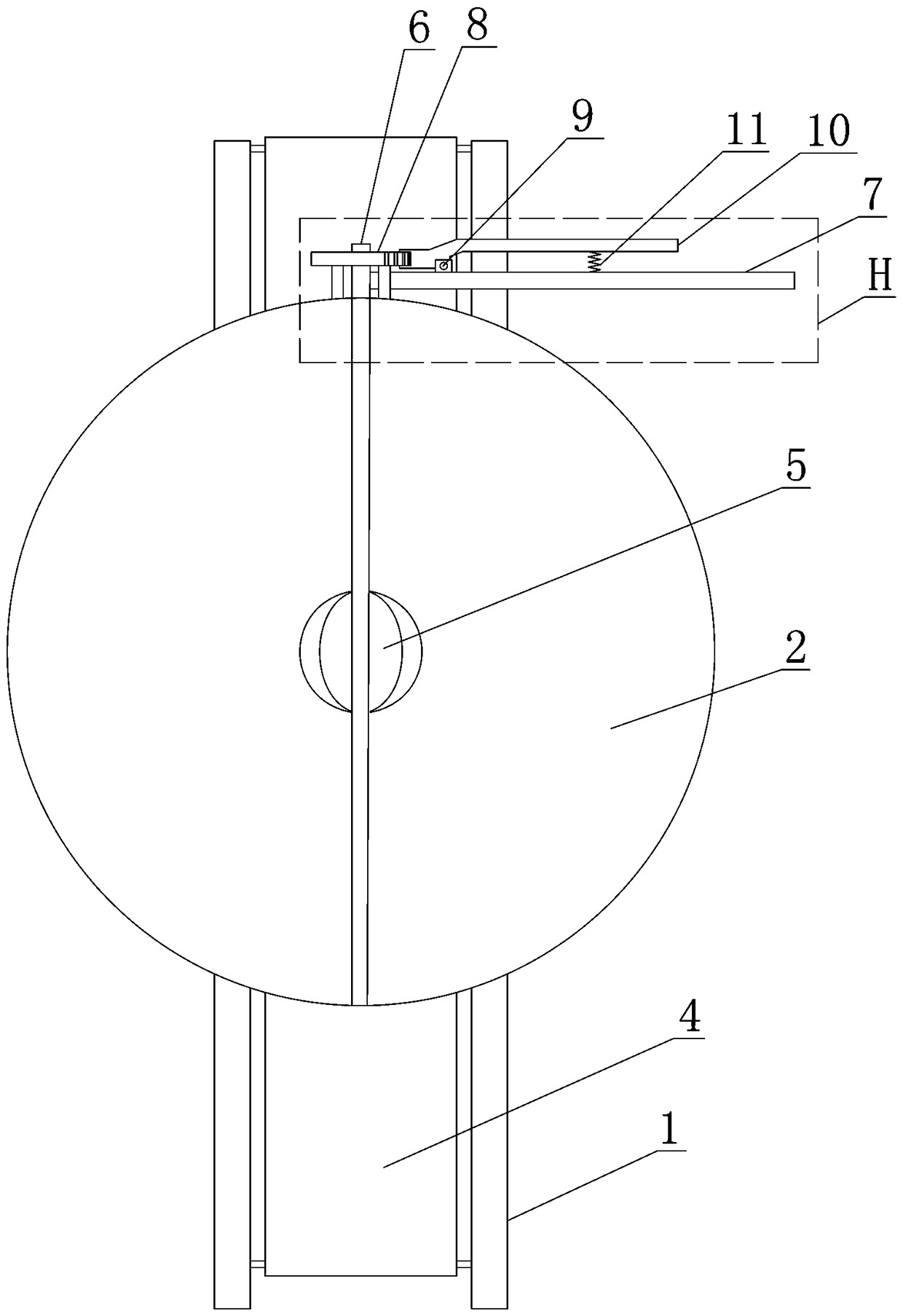
[0016] Such as figure 1 , figure 2 , image 3 , Figure 4 As shown, the feeding device in the described wire welding machine includes: a frame 1: an upper hopper 2 is arranged in the frame 1, and the opening of the discharge port of the upper hopper 2 is provided in the upper hopper 2 The lower material regulating valve is provided with a lower hopper 3 on the frame 1 below the upper hopper 2, the outlet of the upper hopper 2 is connected to the inlet of the lower hopper 3 through a telescopic connection sleeve assembly, and the outlet of the lower hopper 3 The frame 1 below the mouth is provided with a conveyor belt for receiving the powder output from the lower hopper 3, and conveying the accepted powder to the channel steel belt drawn by the forming unit of the welding wire machine and rolled into a U-shaped section. 4. On the frame 1 b...


PUM


Abstract

The invention discloses a feeding device in a wire welding machine. The feeding device comprises a rack; the rack is internally provided with an upper hopper; a discharging adjusting valve for controlling the opening degree of a discharging outlet of the upper hopper is arranged in the upper hopper; a lower hopper is arranged at the position, below the upper hopper, of the rack; the discharging outlet of the upper hopper is connected with a feeding inlet of the lower hopper through a telescopic connection casing pipe assembly; a conveying belt is arranged at the position, below a discharging outlet of the lower hopper, of the rack, and is used for bearing powder conveyed out by the lower hopper and conveying the borne powder to a channel steel belt pulled by a forming unit of the wire welding machine and rolled to be provided with a U-type section; and a guide assembly for smoothly guiding the powder output by the lower hopper to the conveying belt is arranged at the position, betweenthe lower hopper and the conveying belt, of the rack. The feeding device in the wire welding machine has the advantages that (1) the discharging amount of the powder can be effectively controlled, andcontrol and adjustment are convenient; and (2) the powder can be smoothly guided to the conveying belt and does not leak when discharged to the conveying belt, powder waste is reduced, and the production cost of enterprises is effectively reduced.

Description

technical field [0001] The invention relates to the technical field of flux-cored welding wire production auxiliary equipment, in particular to a wire scraping device matched with a welding wire machine. Background technique [0002] Flux-cored welding machine is a commonly used flux-cored wire production equipment, including a device for pulling flat steel strips and rolling the flat steel strips into U-shaped cross-section channel steel strips and rolling the channel steel strips into tube shapes. Forming unit, and feeding device for delivering flux powder to channel steel belt. The production process of the flux-cored wire machine is: the forming unit pulls the flat steel strip coiled on the reel into the wire welding machine, and rolls the flat steel strip into a U-shaped cross-section channel steel strip, and then sends the flux through the feeding device The powder is conveyed and filled in the U-shaped groove of the channel steel belt, and then the forming unit seals...

Claims


Application Information

Patent Timeline
Patent Type & Authority Applications(China)
IPC IPC(8): B65G47/19
CPCB65G47/19
Inventor 黄卫星
Owner JIANGSU XINZHOU WEAR-RESISTANT TECH CO LTD
Why Eureka
Try Eureka