
Soil body cutting device for shield tunneling machine and application method of soil body cutting device

A technology of a cutting device and an application method, which is applied in the field of shield machines, can solve problems such as weak soil cutting ability, offset between the construction axis and the design axis, and a small amount of tools, so as to enhance the ability of cutting strata and prevent deviation. The effect of reducing the shifting phenomenon and shortening the construction period

Pending Publication Date: 2018-09-25
EAST CHINA JIAOTONG UNIVERSITY
View PDF0 Cites 0 Cited by
  • Summary
  • Abstract
  • Description
  • Claims
  • Application Information

AI Technical Summary

Problems solved by technology

However, the traditional rotary cutter head shield machine has poor performance in the control of the previous method, resulting in a certain deviation between the construction axis and the design axis.
[0004] At the same time, when the traditional rotary cutter head rotates and cuts the excavation surface, it needs the shield shell of the shield machine to provide torque, so the shield shell will inevitably be twisted during the excavation construction process, so the shield tunnel that has just been assembled It will bear a certain torsional force, and its segments are prone to misalignment, deformation and even damage, which will lead to water leakage in the tunnel
At the same time, the traditional rotary cutterhead secures the cutter on the cutterhead surface, the cutting ability of the cutter on the soil is weak, and the total amount of cutters is small

Method used


Image

  • Soil body cutting device for shield tunneling machine and application method of soil body cutting device
  • Soil body cutting device for shield tunneling machine and application method of soil body cutting device
  • Soil body cutting device for shield tunneling machine and application method of soil body cutting device

Examples


Embodiment

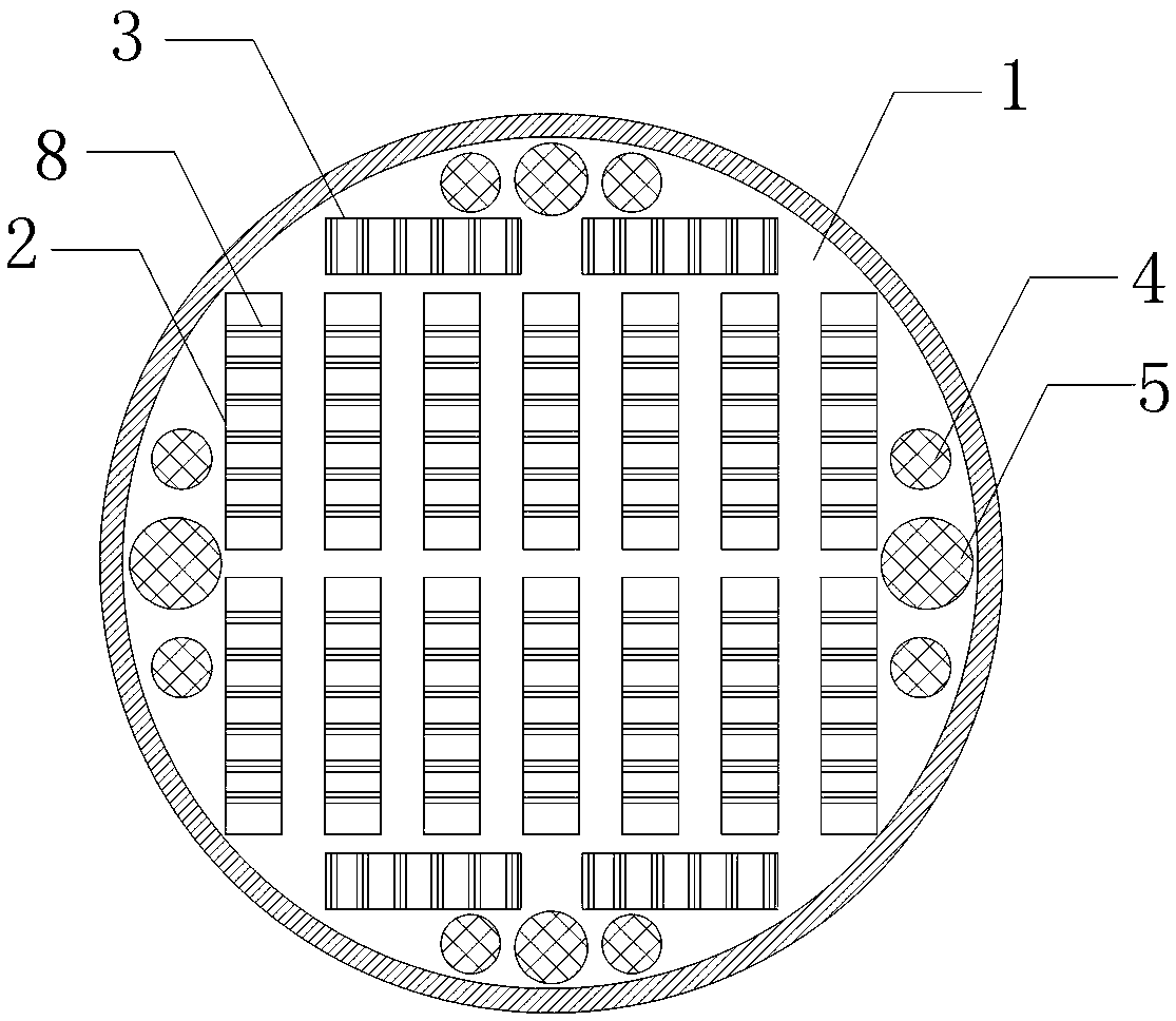
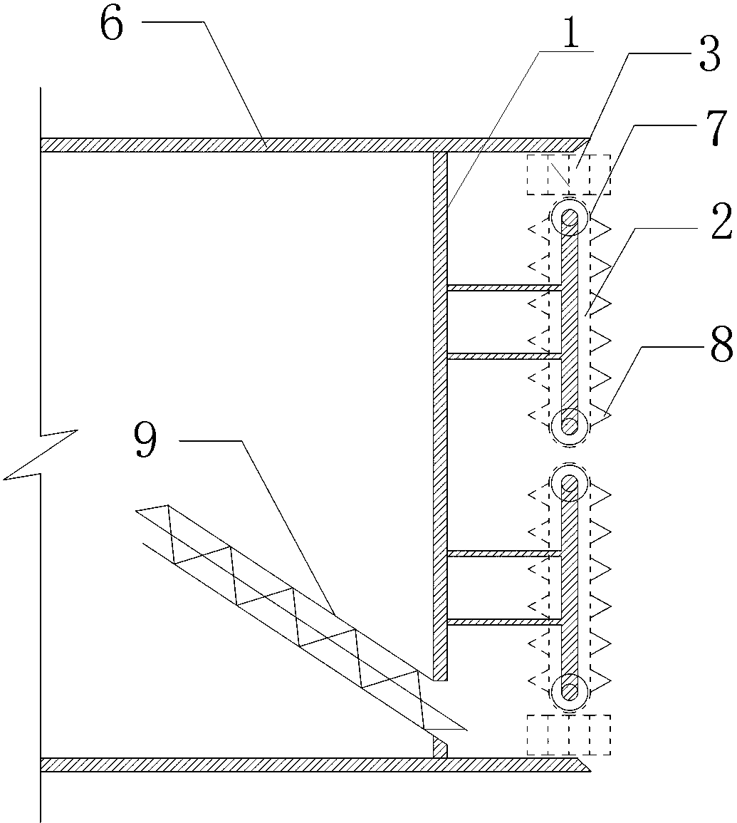
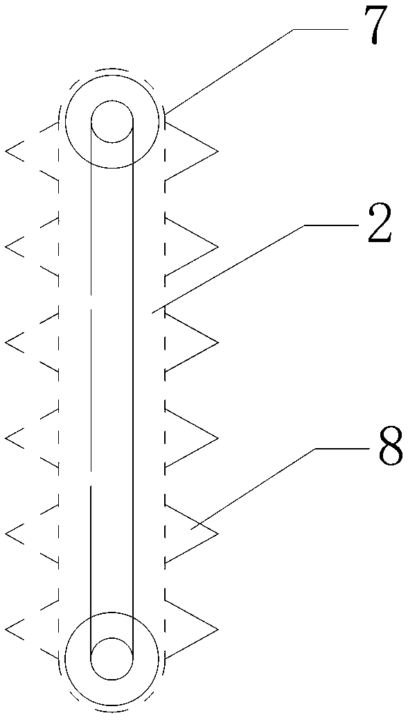
[0023] Example: such as Figure 1-3 As shown, this embodiment specifically relates to a shield machine soil cutting device and its application method. The soil cutting device is arranged on the soil bulkhead 1 at the front end of the shield machine, and includes a vertical knife chain 2, a transverse The knife chain 3 , the small rotating cutter head 4 and the small rotating cutter head 5 realize the control of the tunneling posture of the shield machine by controlling the rotation directions of the vertical knife chain 2 and the horizontal knife chain 3 .

[0024] Such as Figure 1-3 As shown, the front end of the shield shell 6 of the shield machine in this embodiment is a soil cabin, and the soil cutting device is specifically provided on the soil bulkhead 1 at the front end of the soil cabin, including a vertical knife chain 2 and a horizontal knife chain 3 , rotating small cutterhead 4, rotating small cutterhead 5. The vertical knife chains 2 are arranged in the middle ...


PUM


Abstract

The invention discloses a soil body cutting device for a shield tunneling machine and an application method of the soil body cutting device. The soil body cutting device comprises a plurality of vertical knife chains, transverse knife chains and rotary small knife discs which are arranged on a soil bin wall board at the front end part of the shield tunneling machine. The tunneling attitude of theshield tunneling machine is adjusted by controlling the rotation directions of the vertical knife chains and / or the transverse knife chains in the tunneling process of the shield tunneling machine. The soil body cutting device has the advantages that by controlling the rotation direction of the knife discs of the soil body cutting device, the tunneling attitude of the shield tunneling machine canbe flexible adjusted, so that the skewing phenomenon in the tunneling process is prevented; and the knife chains are capable of cutting a stratum with strong power, so that the tunneling speed of theshield tunneling machine can be increased, the construction period can be shortened, and the replacement frequency of knives can be reduced.

Description

technical field [0001] The invention relates to the technical field of shield machines, in particular to a shield machine soil cutting device and an application method thereof. Background technique [0002] The overall mass of the shield machine is relatively large, and its front end contains various power equipment, cutter heads, soil bulkheads, etc., resulting in the weight of the head of the shield machine being greater than the weight of its tail. When the shield machine is in the excavation construction process, it is very easy for the front part of the shield machine to be pressed into the soil layer, resulting in a downward deviation of the forward direction of the shield machine, that is, the phenomenon of pinching, and the traditional shield machine generally adopts a rotating Type cutter head, the forward direction and posture of the shield machine can only be controlled and adjusted by the jack at the tail of the shield machine. However, this method of relying on...

Claims


Application Information

Patent Timeline
IPC IPC(8): E21D9/08E21D9/093
CPCE21D9/08E21D9/093
Inventor 黄大维冯青松徐金辉杨成忠梁玉雄王威徐松黄旭东郑金任
Owner EAST CHINA JIAOTONG UNIVERSITY
Learn More