Paper cup collecting and piling system on cup handle paper cup shaping machine

A technology for forming machines and paper cups, applied in the field of paper cup collection and stacking systems, can solve the problems of wasting labor, low work efficiency, easy to fall, etc., and achieve the effects of facilitating conveying and stacking, improving work efficiency, and reducing labor.

Pending Publication Date: 2018-09-25
京山大昌商贸股份有限公司
View PDF1 Cites 2 Cited by
  • Summary
  • Abstract
  • Description
  • Claims
  • Application Information

AI Technical Summary

Problems solved by technology

[0003] The purpose of the present invention is to aim at the present, in order to prevent hot hands, a handle will be pasted on the cup wall of the paper cup, the middle of the handle will be pasted on the cup wall, and the two ends of the handle are movable ends. There is a certain gap, and the handle can be used as a handle by folding the two ends of the handle together when using it. China Patent Network CN103317776B has announced a "suction and release double paper mechanism of sticky handle type paper cup forming machine", which is used for one-time production. After the paper cups are formed, due to the existence of the handle, the gap between the paper cups is large when the paper cup forming machine collects the paper cups, which makes the paper cup tubes loose and easy to fall, which is not conducive to packaging and stacking. At the same time, it takes up more stacking space. After the paper cups are collected It is also necessary to batch and stack manually, which is a waste of labor, and at the same time, the work efficiency is low. However, a paper cup collection and stacking system for cups and paper cup forming machines is provided.

Method used


Image

  • Paper cup collecting and piling system on cup handle paper cup shaping machine
  • Paper cup collecting and piling system on cup handle paper cup shaping machine
  • Paper cup collecting and piling system on cup handle paper cup shaping machine

Examples


Embodiment Construction

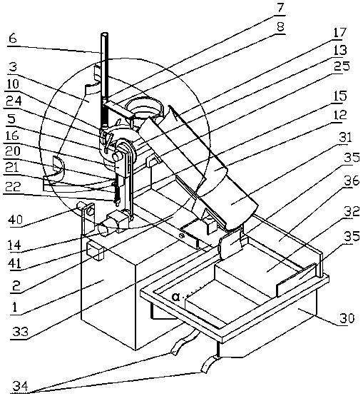
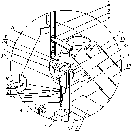
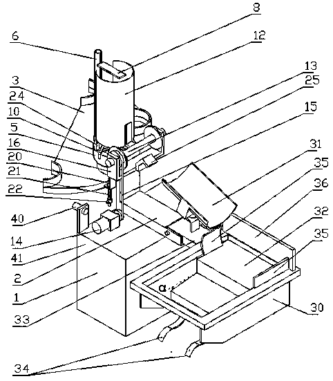
[0011] As shown in the drawings, the present invention includes a base 1, a paper cup collecting device, a batch unloading device and an automatic stacking device. The base 1 is provided with an L-shaped support frame 2, and the base 1 is located on the side of the discharge tray 3 of the paper cup forming machine. , the paper cup collection device includes a cylindrical cup holder 5, a guide cylinder 6, a guide rod 7 and a pressing plate 8, the cylindrical cup holder 5 is installed on one end of the L-shaped support frame 2, and is located above the discharge tray 3 of the paper cup forming machine There are a plurality of first elastic stoppers 10 in an annular array on the top of the cylindrical cup holder 5, and the movable ends of the plurality of first elastic stoppers 10 are respectively inclined to the center of the cylindrical cup holder 5, and the cylindrical cup holder The top of the frame 5 is provided with a guide cylinder 6 connecting the screw rod, and one end of...


PUM


Abstract

The invention provides a paper cup collecting and piling system on a cup handle paper cup shaping machine. The system comprises a base (1), a paper cup collecting device, a batch blanking device and an automatic piling device, wherein the paper cup collecting device comprises a tubular cup placing frame (5), a guide tube (6), a guide rod (7) and a press plate (8); the batch blanking device comprises a blanking tube (12), a rotating shaft (13), a rotating shaft driving motor (14), a transmission chain (15) and a chain tensioning assembly; the automatic piling device comprises a blanking frame (30), a material collecting chute (31) and a step type slide plate (32). The paper cup collecting and piling system has the advantages that the paper cup collecting device collects the paper cups withcup handles; meanwhile, the paper cup tubes are tightly piled; the conveying and piling are convenient; through the batch blanking device, the paper cup tubes can be fast divided into batches; throughthe automatic piling device, the paper cup tubes divided into batches can be automatically and tidily piled in a packaging box; the labor work is reduced; meanwhile, the work efficiency is improved.

Description

technical field [0001] The invention relates to the technical field of paper cup production, in particular to a paper cup collecting and stacking system used on a cup forming machine for paper cups. Background technique [0002] At present, in order to prevent hot hands, a handle is pasted on the cup wall of the paper cup, the middle of the handle is pasted on the cup wall, and the two ends of the handle are movable ends. Folding the two ends of the handle together can be used as a handle. China Patent Network CN103317776B has announced a "sticky handle type paper cup forming machine suction and release double paper mechanism", which is used for one-time production of paper cups with handles. After the paper cups are formed Due to the existence of the handle, the gap between the paper cups is large when the paper cup forming machine collects the paper cups, which makes the paper cup tubes loose and easy to fall, which is not conducive to packaging and stacking. At the same t...

Claims


Application Information

Patent Timeline
IPC IPC(8): B31D5/00B31B50/94
CPCB31B50/94B31D5/00
Inventor 王东访
Owner 京山大昌商贸股份有限公司
Why Eureka
Try Eureka