
IGBT driving circuit of motor controller, and motor controller

A motor controller and drive circuit technology, which is applied in the direction of motor control, amplifier protection circuit layout, DC motor deceleration device, etc., to achieve the effects of rapid action, shortened protection time, and timely protection

Pending Publication Date: 2018-09-21
JING JIN ELECTRIC TECHNOLOGIES (BEIJING) CO LTD
View PDF12 Cites 13 Cited by
  • Summary
  • Abstract
  • Description
  • Claims
  • Application Information

AI Technical Summary

Problems solved by technology

[0003] At present, there are few researches on the functional safety design of the vehicle drive motor system in China. The motor controller is the core component of the vehicle power. Therefore, there is an urgent need for a technical solution that can improve the functional safety of the motor controller.

Method used


Image

  • IGBT driving circuit of motor controller, and motor controller
  • IGBT driving circuit of motor controller, and motor controller
  • IGBT driving circuit of motor controller, and motor controller

Examples


Embodiment Construction

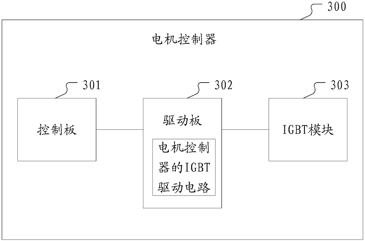
[0032] As the core component of the vehicle's power, the motor controller is composed of many parts, among which the drive circuit is the key part, and it is also the focus of the functional safety design of the vehicle drive motor system. The embodiment of the present application provides an IGBT driving circuit of a motor controller, so as to quickly ensure the safety of the IGBT module and the motor controller when a failure of the IGBT module is detected.

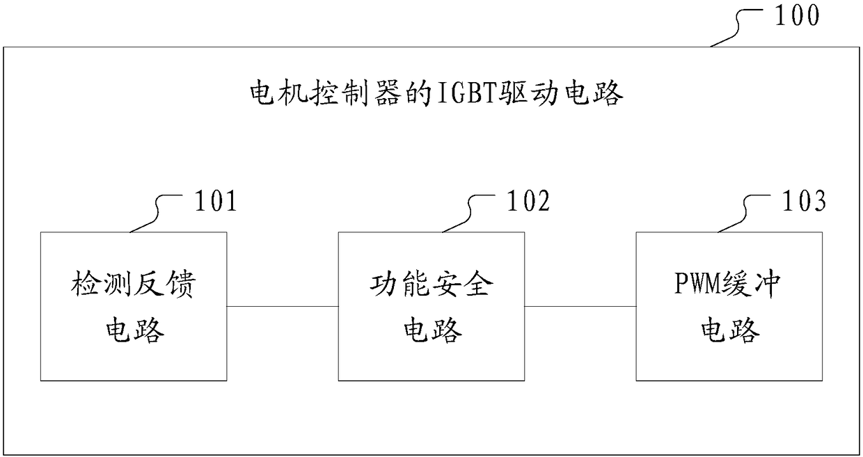
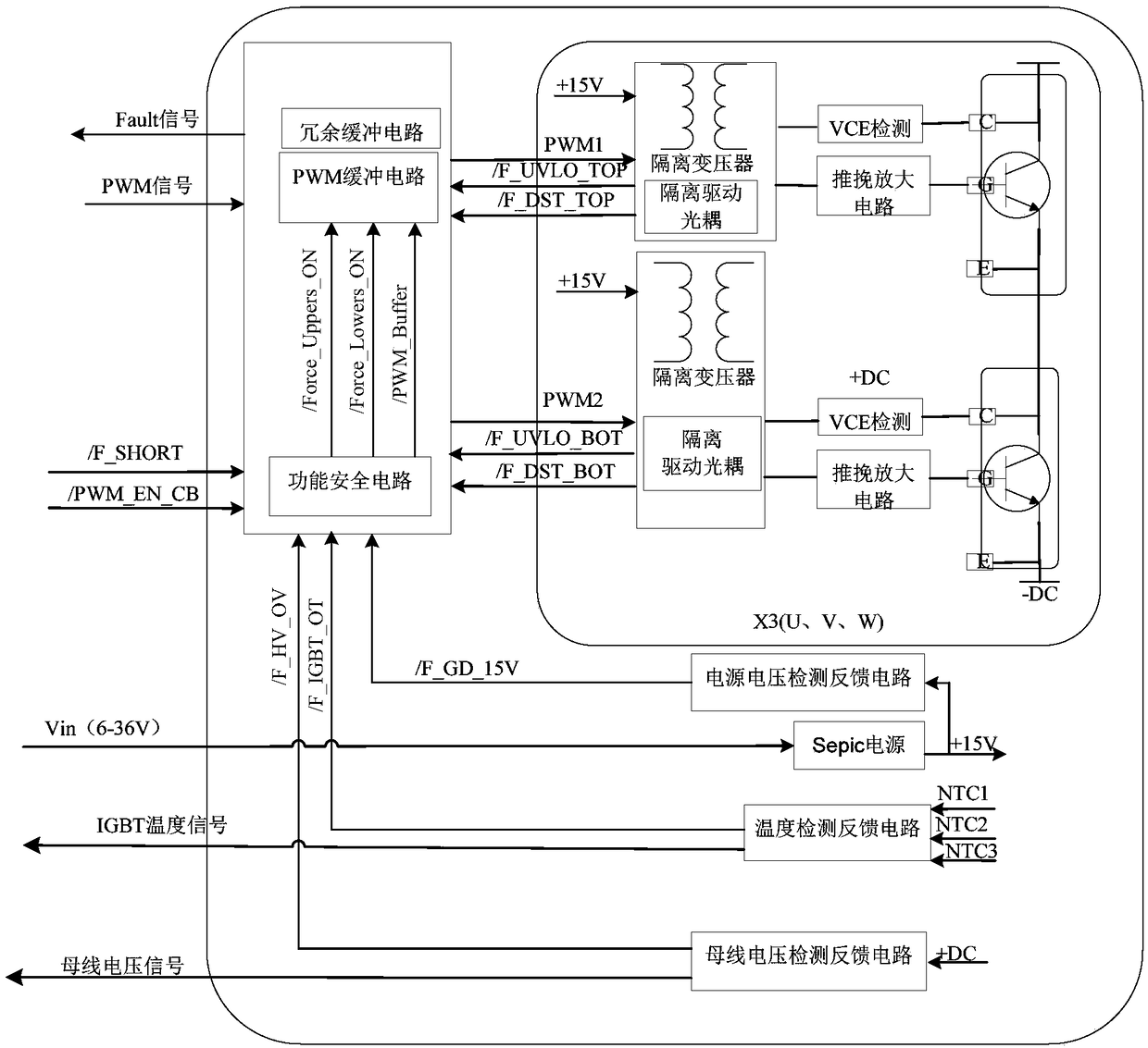
[0033] figure 1 It is a block diagram of the IGBT drive circuit of the motor controller of an embodiment of the present invention, see figure 1 , The IGBT driving circuit of the motor controller of the embodiment of the present invention includes: a functional safety circuit 102 arranged on the motor controller driving board, and a detection feedback circuit 101 and a pulse width modulation PWM buffer respectively connected to the functional safety circuit 102 circuit 103;

[0034] The detection feedback circuit 101 d...


PUM


Abstract

The invention discloses an IGBT driving circuit of a motor controller and a motor controller. The IGBT driving circuit comprises a functional safety circuit disposed on a motor controller driving board, and a detection feedback circuit and a pulse width modulation (PWM) buffer circuit which are connected to the functional safety circuit. The detection feedback circuit detects an IGBT module of themotor controller and sends a specified fault signal to the functional safety circuit when detecting a specified fault of the IGBT module. The functional safety circuit, after making a judgment according to a preset fault handling rule and the received specified fault signal, outputs a corresponding control signal to the PWM buffer circuit. The PWM buffer circuit generates a PWM signal for drivingthe IGBT module according to the corresponding control signal, and controls the on-off state of the IGBT module to protect the IGBT module. The IGBT driving circuit has various protection functions,improves the stability and safety of the IGBT, and can achieve quick operation and timely protection.

Description

technical field [0001] The invention relates to the technical field of motor controllers, in particular to an IGBT drive circuit of the motor controller and the motor controller. Background technique [0002] With the extensive use of electrical and electronic equipment in the automotive field, especially in the control system, some new safety issues continue to emerge, and dangerous accidents occur frequently, which makes major automobile companies pay more and more attention to functional safety, and also prompts the International Organization for Standardization (ISO) Researched and developed the functional safety international standard ISO 26262 specifically for automotive electronic and electrical systems. This standard involves the entire vehicle safety lifecycle and its management process of automotive electronic and electrical systems, and puts forward high requirements for automotive companies and their parts companies. [0003] At present, there are few researches...

Claims


Application Information

Patent Timeline
IPC IPC(8): H02H7/20
CPCH02H7/205H02H7/1225H02P29/024H02P29/028H02P29/68H02P29/0241H02P29/026H02P3/12H03K17/0828H03F3/3086H03F2200/534H03F1/52H03K2217/0081H03K17/78H03K17/691H03F3/26
Inventor 谷冬平万富翔董仁俊
Owner JING JIN ELECTRIC TECHNOLOGIES (BEIJING) CO LTD
Learn More