
Liquid separator and heat exchanger with same

A technology of liquid separator and heat exchanger, which is applied in the direction of evaporator/condenser, refrigeration and liquefaction, lighting and heating equipment, etc. It can solve the problems of difficult installation of liquid separator, and achieve the solution of difficult installation and simplified The effect of installation

Pending Publication Date: 2018-09-21
BEIJING SINOREFINE AIR CONDITIONING TECH +1
View PDF6 Cites 2 Cited by
  • Summary
  • Abstract
  • Description
  • Claims
  • Application Information

AI Technical Summary

Problems solved by technology

[0005] The main purpose of the present invention is to provide a liquid separator and a heat exchanger with it, so as to solve the problem that the liquid separator in the prior art is difficult to install

Method used


Image

  • Liquid separator and heat exchanger with same
  • Liquid separator and heat exchanger with same
  • Liquid separator and heat exchanger with same

Examples


Embodiment Construction

[0037] It should be noted that, in the case of no conflict, the embodiments in the present application and the features in the embodiments can be combined with each other. The present invention will be described in detail below with reference to the accompanying drawings and examples.

[0038] It should be pointed out that the following detailed description is exemplary and intended to provide further explanation to the present application. Unless defined otherwise, all technical and scientific terms used herein have the same meaning as commonly understood by one of ordinary skill in the art to which this application belongs.

[0039] It should be noted that the terminology used here is only for describing specific implementations, and is not intended to limit the exemplary implementations according to the present application. As used herein, unless the context clearly dictates otherwise, the singular is intended to include the plural, and it should also be understood that wh...


PUM


Abstract

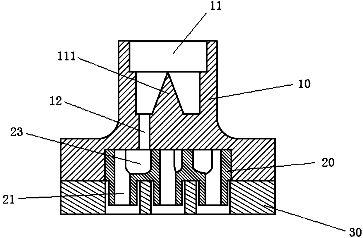
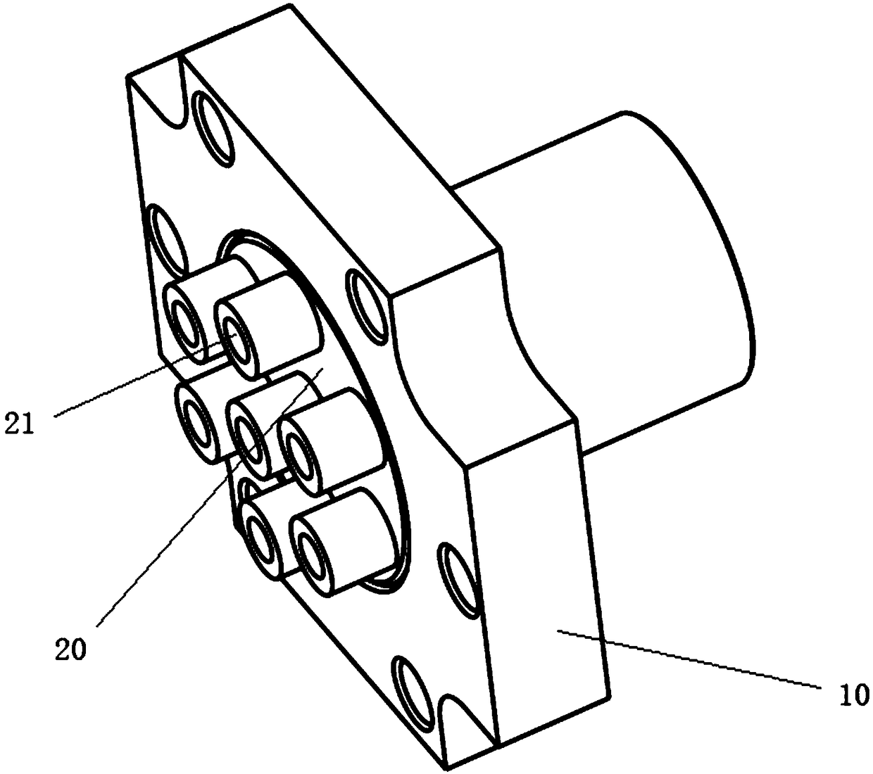
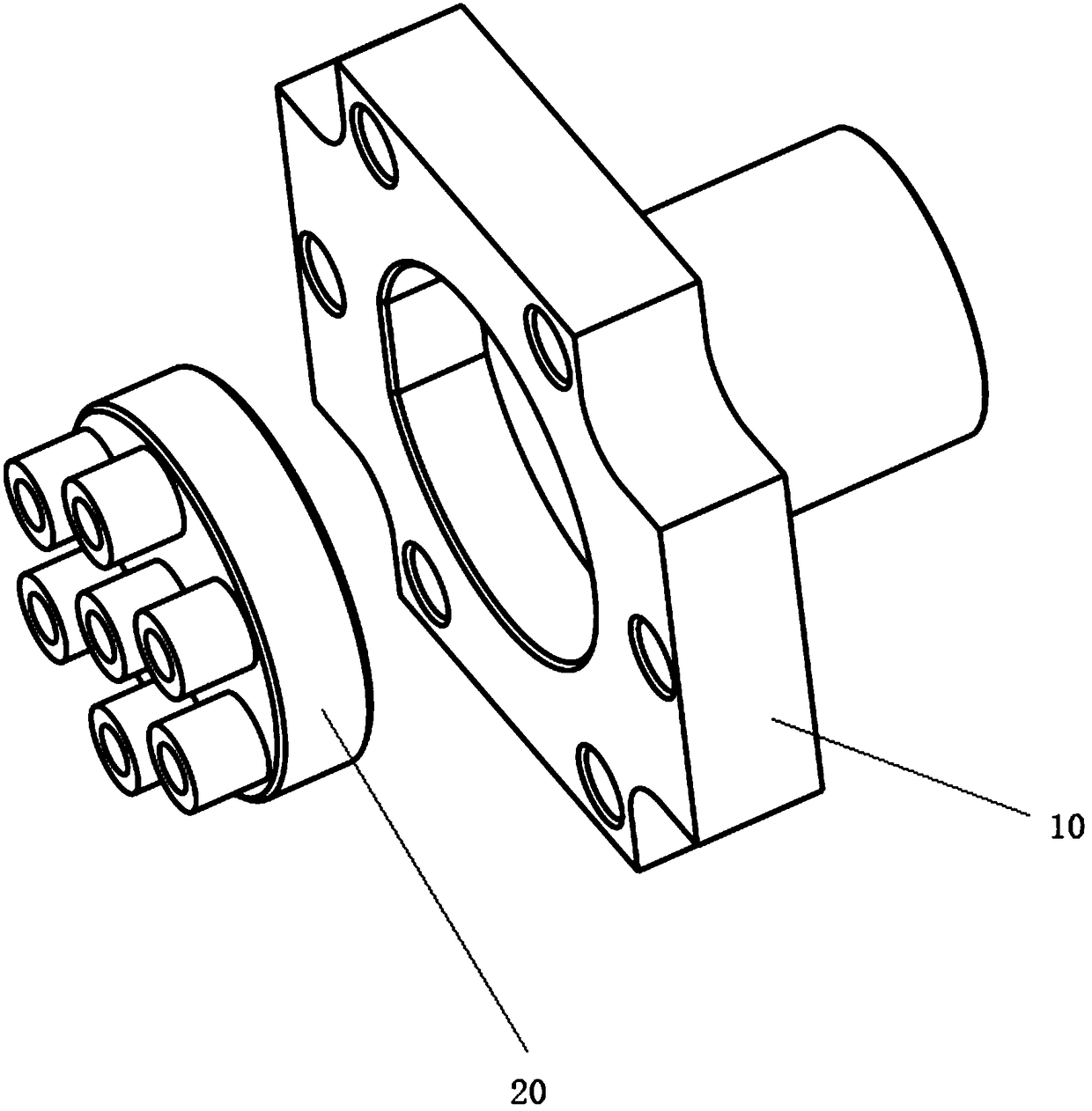
The invention provides a liquid separator and a heat exchanger with the liquid separator. The liquid separator comprises a liquid separating flange and a flow division portion. The liquid separating flange comprises a liquid separating cavity and a plurality of liquid separating holes communicating with the liquid separating cavity. The flow division portion is connected with the liquid separatingflange and comprises a plurality of flow division holes. The multiple flow division holes communicate with the corresponding liquid separating holes correspondingly. By means of the liquid separator,the problem that in the prior art, a liquid separator is difficult to install is solved.

Description

technical field [0001] The invention relates to the field of liquid separators, in particular to a liquid separator and a heat exchanger having the same. Background technique [0002] In the refrigeration system, the refrigerant entering the evaporator is in a gas-liquid two-phase state. In a multi-circuit evaporator, it is easy to cause uneven distribution of gas and liquid, resulting in a decrease in the heat exchange efficiency of the evaporator. In order to solve this problem, the evaporator will be equipped with a liquid separator to evenly distribute the gas-liquid two-phase refrigerant to each circuit of the evaporator. [0003] The form of the liquid separator is generally designed according to the form of the evaporator, and the most common form is the form of a liquid separator with a capillary tube. The inlet of the liquid distribution head is provided with a throttle ring with a narrow mouth. After mixing the gas and liquid in the refrigerant, it enters a distri...

Claims


Application Information

Patent Timeline
Patent Type & Authority Applications(China)
IPC IPC(8): F25B41/00F25B39/02F25B41/40
CPCF25B39/028F25B41/00
Inventor 陈亮亮陈晓阳孙文倩李奇
Owner BEIJING SINOREFINE AIR CONDITIONING TECH
Learn More