Pneumatic relay
A technology for relays and intake valves, applied to engine components, valve details, multi-way valves, etc., can solve the problems of large jump value, large effective area, and large insensitive area, and achieve area reduction and industrial Great benefits and lower machining accuracy
- Summary
- Abstract
- Description
- Claims
- Application Information
AI Technical Summary
Problems solved by technology
Method used
Image
Examples
Embodiment 1
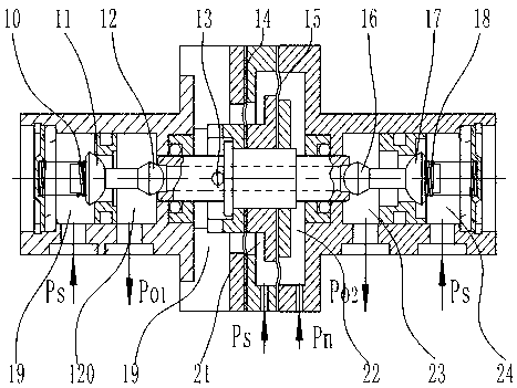
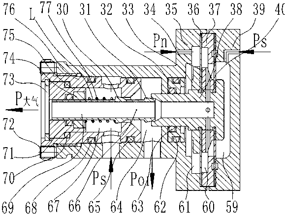
[0049] like image 3 As shown, a pneumatic relay includes two parts: the base pressure body and the back pressure body: the back pressure housing 35 of the back pressure body has built-in threads, and the intake valve seat 76 of the relay is connected by thread Screw into the back pressure housing 35, so that the intake valve seat 76 can move axially in the back pressure housing 35, and fix it with the set screw 72 after the movement is completed; the tail of the intake valve core 30 of the relay grows to form a tail The straight shank section L, the tail straight shank section L is inserted into the assembly formed by the pressure ring 74 and the guide sleeve 75, and then installed in the intake valve seat 76 as a whole; the intake valve core 30 and the exhaust valve core of the relay The center of 31 is provided with a through hole, which is docked with the through hole in the center of the diaphragm seat 38 of the relay to form an exhaust passage 69, and the exhaust passage...
Embodiment 2
[0059] like Figure 4 As shown, a pneumatic relay includes two parts: the base pressure body and the back pressure body: the back pressure housing 35 of the back pressure body has built-in threads, and the intake valve seat 76 of the relay is connected by thread Screw into the back pressure housing 35, so that the intake valve seat 76 can move axially in the back pressure housing 35, and fix it with the set screw 72 after the movement is completed; the tail of the intake valve core 30 of the relay grows to form a tail The straight shank section L, the tail straight shank section L is inserted into the assembly formed by the pressure ring 74 and the guide sleeve 75, and then installed in the intake valve seat 76 as a whole; the intake valve core 30 and the exhaust valve core of the relay The center of 31 is provided with a through hole, which is docked with the through hole in the center of the diaphragm seat 38 of the relay to form an exhaust passage 69, and the exhaust passag...
Embodiment 3
[0062] like Figure 7 , Figure 8 As shown, the Ps gas path on the upper part of the base pressure shell is adjusted, and the gas source directly enters the working chamber 60, so that the working chamber 60 serves as the base pressure chamber, and the working chamber 59 serves as the evacuation chamber, and other unrelated structures do not change.
[0063] Description of working principle:
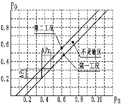
[0064] When the position of the diaphragm is manufactured and assembled, the results are not ideal, and at the same time, the Figure 5 It can be seen that the diaphragm has different equivalent diameters, that is, different effective working areas, in different positions. By adjusting the intake valve seat 76, the exhaust valve core 31 moves axially to change the relative length of the exhaust valve core 31, and the effective working area becomes a controllable parameter. suppression. In the design, the sealing specific pressure of the intake valve core is maintained, and the diamet...
PUM
 Abstract
Description
Claims
Application Information
 - Generate Ideas
- Intellectual Property
- Life Sciences
- Materials
- Tech Scout
- Unparalleled Data Quality
- Higher Quality Content
- 60% Fewer Hallucinations
Browse by: Latest US Patents, China's latest patents, Technical Efficacy Thesaurus, Application Domain, Technology Topic, Popular Technical Reports.
© 2025 PatSnap. All rights reserved.Legal|Privacy policy|Modern Slavery Act Transparency Statement|Sitemap|About US| Contact US: help@patsnap.com


