
Industrial exoskeleton with vibration reduction function

An exoskeleton and industrial technology, which is applied in the field of industrial machinery exoskeleton, can solve the problems of inability to effectively reduce vibration and insufficient deflection degree of freedom, and achieve the effect of high degree of freedom, absorption and buffering of vibration, and auxiliary support stability

Pending Publication Date: 2018-09-21
CHENGDU AIRCRAFT INDUSTRY GROUP
View PDF15 Cites 8 Cited by
  • Summary
  • Abstract
  • Description
  • Claims
  • Application Information

AI Technical Summary

Problems solved by technology

[0009] Aiming at the defects that the traditional industrial exoskeleton cannot effectively reduce the vibration generated during work, the lower limbs twist along the axial direction of the lower limbs, and the deflection degree of freedom is insufficient, the purpose of the present invention is to provide an industrial exoskeleton with a vibration reduction function The bone can effectively reduce the vibration suffered by workers during work, the lower limbs can rotate along the axial direction of the lower limbs, and have sufficient yaw freedom.

Method used


Image

  • Industrial exoskeleton with vibration reduction function
  • Industrial exoskeleton with vibration reduction function
  • Industrial exoskeleton with vibration reduction function

Examples


Embodiment 1

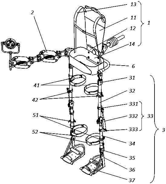
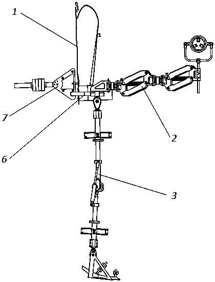
[0036] like Figure 1-3 As shown, an industrial exoskeleton with vibration damping function includes an upper trunk support 1 with a balance mechanism 7 installed on the back, and a hip joint 6 is fixedly connected to the lower part of the upper trunk support 1; one side of the hip joint 6 A damping and vibration-absorbing mechanical arm 2 is movably connected, and lower limb assemblies 3 are movably connected to the left and right ends of the hip joint 6 .

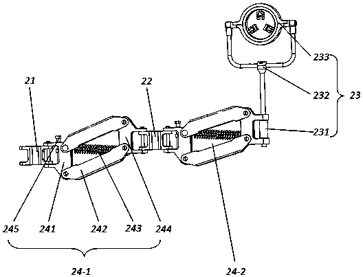
[0037] The damping and vibration damping mechanical arm 2 includes a waist arm connecting block 21 , an intermediate connecting block 22 and a clamping device 23 . The right end damping and vibration damping assembly 24-2 is hinged; the free end of the left end damping and vibration damping assembly 24-1 is hinged with one end of the waist-arm connecting block 21, and the other end of the waist-arm connecting block 21 is hinged with the industrial exoskeleton; The free end of the damping and damping assembly 24-2 is clam...

Embodiment 2

[0042] This embodiment is further optimized on the basis of Embodiment 1, such as image 3 and Figure 4 As shown, the middle of the front-end positioning block 241 is also provided with an adjustment installation hole, and a spring adjuster 245 is installed in the adjustment installation hole through a thread; the spring adjuster 245 is connected to one end of the spring damper 243 . The spring damper 243 includes a damping spring and a retractable adjusting rod, the adjusting rod is located inside the spring, and one end of the adjusting rod is connected with the fixing nut on the stud of the spring adjuster 245 .

[0043] When the initial height of the spring damper 243 needs to be adjusted, the spring adjuster 245 is rotated, so that the stud in the technetium spring adjuster 245 drives the fixing nut on it to move up and down, and the fixing nut drives the spring damper 243 to move up and down to complete the initial height. adjust. The spring damper 243 is divided into...

Embodiment 3

[0046] This embodiment is further optimized on the basis of Embodiment 1, such as figure 1 , image 3 , Image 6 As shown, the clamping device 23 includes a connection sleeve 231 and a pan / tilt frame 232, the connection sleeve 231 is clamped with the free end of the right damping and vibration reduction assembly 24, and the bottom of the pan / tilt frame 232 is screwed to the connection Inside the sleeve 231 , a tool fixing block 233 is clamped on the upper part of the pan / tilt frame 232 ;

[0047] The tool fixing block 233 includes an upper semicircular hoop 001, a lower semicircular hoop 002, and a fixing ring 003; the lower semicircular hoop 002 is a semicircular structure with pillars on the left and right sides, and the pillars on the left and right sides are provided with hoop connection grooves There are bosses on the left and right sides of the upper half-circle hoop 001 that match the hoop connecting grooves on the left and right sides of the lower half-circle hoop 00...


PUM


Abstract

The invention discloses an industrial exoskeleton with a vibration reduction function. The industrial exoskeleton comprises an upper trunk support. A balance mechanism is mounted on the back of the upper trunk support, and a hip joint is fixedly connected with the lower portion of the upper trunk support; a damping vibration reduction mechanical arm is movably connected with a side of the hip joint, and lower limb assemblies are movably connected with the left side and the right side of the hip joint. Vibration on the damping vibration reduction mechanical arm in working procedures can be reduced by damping vibration reduction assemblies of the damping vibration reduction mechanical arm. Lower limbs can move under the condition of a high degree of freedom by the aid of thigh bearings and shank bearings of the lower limb assemblies. Leg support assemblies are arranged on the lower limb assemblies, and the waists and the knees of human bodies can be supported by adjustable gas springs ofthe leg support assemblies. The industrial exoskeleton has the advantages that the vibration generated in the working procedures can be absorbed and cushioned by the novel industrial exoskeleton, accordingly, vibration load in wearers can be relieved to a great extent, the lower limb assemblies can flexibly move along with the lower limbs of wearing personnel under the condition of the high degree of freedom, and the waists and the knees of workers can be stably supported and can be effectively protected.

Description

technical field [0001] The invention relates to the technical field of industrial mechanical exoskeletons, in particular to an industrial exoskeleton with vibration reduction function. Background technique [0002] An industrial exoskeleton is a wearable mechanical device that is mainly used in industrial production lines. Industrial exoskeletons can greatly reduce the force required by workers to lift workpieces, improve worker productivity, reduce worker loads, and prevent workers from musculoskeletal damage. [0003] The industrial exoskeleton is different from the general power-assisted exoskeleton. The industrial exoskeleton is a powerless device that helps the human body to carry and protect the human body through the relevant mechanical structure; A device that realizes human-machine coupling to help the wearer perform movement. [0004] The main function of industrial exoskeleton is to cooperate with workers to work, improve work efficiency, and protect workers' mu...

Claims


Application Information

Patent Timeline
IPC IPC(8): B25J9/00B25J19/00
CPCB25J9/0006B25J19/0091
Inventor 朱隽沛夏继军
Owner CHENGDU AIRCRAFT INDUSTRY GROUP
Learn More