Passive optical label and optical identification label system

A passive light and label technology, applied in the field of communication, can solve the problems that the output power of photovoltaic cell components is affected by the area, and the miniaturization of passive light labels cannot be realized, so as to improve the energy conversion efficiency and expand the application range.

Inactive Publication Date: 2018-09-18
ALUKSEN OPTOELECTRONICS CO LTD
View PDF9 Cites 0 Cited by
  • Summary
  • Abstract
  • Description
  • Claims
  • Application Information

AI Technical Summary

Problems solved by technology

[0006] The purpose of the present invention is to provide a passive optical label to solve the problem that the existing passive optical label cannot realize the miniaturization of the passive optical label because the output power of the photovoltaic cell module is affected by the area

Method used


Image

  • Passive optical label and optical identification label system
  • Passive optical label and optical identification label system
  • Passive optical label and optical identification label system

Examples


Embodiment Construction

[0028] In order to make the object, technical solution and advantages of the present invention clearer, the present invention will be further described in detail below in conjunction with the accompanying drawings and embodiments. It should be understood that the specific embodiments described here are only used to explain the present invention, not to limit the present invention.

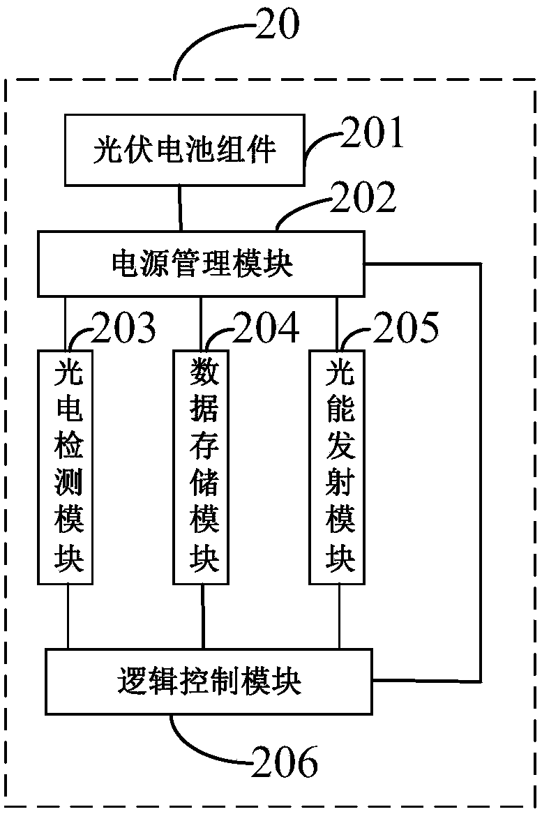
[0029] figure 1 It is a schematic structural diagram of the passive optical label 20 in an embodiment of the present invention, from figure 1 It can be seen from the figure that in this embodiment, the passive optical tag 20 includes a photovoltaic cell assembly 201, a power management module 202, a photoelectric detection module 203, a data storage module 204, a light energy emission module 205, and a logic control module 206. The power management Module 202, photoelectric detection module 203, data storage module 204, light energy emission module 205 and logic control module 206 are integrated o...


PUM


Abstract

The invention provides a passive optical label and an optical identification label system; a high efficiency back-contact photovoltaic battery assembly is employed in a passive optical label; a circuit board with an interdigital electrode is designed so as to realize cascaded and parallel arrangement of a plurality of photovoltaic cells, so the photovoltaic cells in a small area can realize a highoutput power, thus improving the optical signal energy conversion efficiency. The output power of an existing optical label can be reduced when being minisized, so a luminous energy emission module in the optical label cannot emit a needed optical signal, thus affecting the stability of the optical identification label system; the passive optical label can solve said problems, thus greatly expanding the application scope of the optical identification label system.

Description

technical field [0001] The invention belongs to the field of communication, and in particular relates to a passive optical label and an optical identification label system. Background technique [0002] With the development of Internet of Things technology, radio frequency identification (Radio Frequency Identificon, RFID) technology has received more and more attention. The RFID system uses radio frequency electromagnetic waves as the medium for data reading and writing between the reader and the electronic tag. Due to the divergence of the propagation direction of radio frequency electromagnetic waves and the susceptibility to interference from metals, the range of RFID use is limited. Optical identification technology is a new type of label identification technology. It uses optical signals to read and write data labels. Because of the directionality of optical signal propagation, the system does not need to use radio frequency electromagnetic waves, so that the data lab...

Claims


Application Information

Patent Timeline
Patent Type & Authority Applications(China)
IPC IPC(8): G06K19/07G06K19/077
CPCG06K19/0704G06K19/07747
Inventor 刘德昂
Owner ALUKSEN OPTOELECTRONICS CO LTD
Why Eureka
Try Eureka