Differential pressure type flowmeter

A differential pressure flowmeter and fluid technology, applied in the direction of detecting fluid flow by measuring differential pressure, volume/mass flow generated by mechanical effects, etc., can solve the problems of large fluid pressure loss and energy consumption, and achieve small pressure loss, Small size effect

Pending Publication Date: 2018-09-18
FIRSTRATE SENSOR
View PDF9 Cites 5 Cited by
  • Summary
  • Abstract
  • Description
  • Claims
  • Application Information

AI Technical Summary

Problems solved by technology

[0004] The existing differential pressure flowmeter installs a throttling device in the pipeline. When the fluid passes through the throttling device, according to Bernoulli's principle, a differential pressure will be generated before and after the throttling device, and the flow rate is proportional to the square root of the differential pressure. , the flow rate can be calculated by measuring the differential pressure and combining the known fluid conditions and the geometric dimensions of the throttling device and the pipeline. However, because the throttling device is installed in the pipeline, the pressure loss of the fluid in the pipeline is relatively large, and the consumption extra energy

Method used


Image

  • Differential pressure type flowmeter
  • Differential pressure type flowmeter
  • Differential pressure type flowmeter

Examples


Embodiment Construction

[0021] The present invention will be further described below in conjunction with drawings and embodiments.

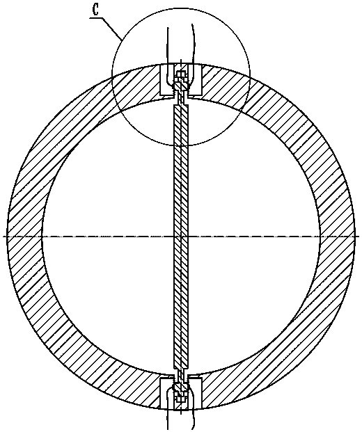
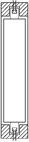
[0022] refer to Figure 1-Figure 4 , this embodiment includes a measuring pipe 1, a pressure sensor 2, an elastic diaphragm 3 and a probe 4, the measuring pipe 1 is provided with a groove at a symmetrical position up and down, and elastic pipes are installed on both sides of the groove inside perpendicular to the fluid direction. Diaphragm 3, the elastic diaphragm 3 is used to convert the lateral pressure of the probe 4 into the deformation of the elastic diaphragm 3, the side of the elastic diaphragm 3 located in the measuring pipe 1 is connected with the probe 4 by welding, and the elastic A pressure sensor 2 is installed on the other side of the diaphragm 3 .

[0023] In this embodiment, the bosses at both ends of the probe are welded to the inner side of the elastic diaphragm in the groove of the measuring pipe by welding, and the pressure sensor is installed on th...


PUM


Abstract

The invention discloses a differential pressure type flowmeter. The flowmeter comprises a measuring pipeline, pressure sensors, elastic diaphragms and a probe, grooves are formed in the positions which are symmetric in the up-and-down direction of the measuring pipeline, the elastic diaphragms are installed on both sides, perpendicular to the direction of fluid, of the interiors of the grooves andused for converting the lateral pressure of the probe to the deformation of the elastic diaphragms, the probe is connected with the faces, located in the measuring pipeline, of the elastic diaphragm,and the pressure sensors are installed on the other faces of the elastic diaphragms. By installing a probe perpendicular to the speed direction of the fluid in the measuring pipeline, pressure difference perpendicular to the surface of the probe is generated on the probe by the fluid when the fluid passes through the probe, the magnitude of the differential pressure has a specific numerical relation with the properties (density and the like) of the fluid, and the differential pressure is measured by the pressure sensors on two ends of the probe to calculate the amount of the flow rate combining with the properties of the fluid and the geometric structure of the pipeline. The flowmeter has the advantages of smaller pressure loss of the fluid, additional energy consumption reduction and thelike.

Description

technical field [0001] The invention relates to a differential pressure flowmeter. Background technique [0002] Flow rate is the amount of fluid flowing through the cross-section of a pipe per unit time, usually represented by mass flow rate or volume flow rate. With the improvement of automation in modern production processes, the requirements for flow measurement have also increased. However, due to the diversity of environments in industrial production processes and the complexity of flow measurement, the selection of flowmeters needs to comprehensively consider range, pressure loss, and fluid flow. nature and other factors. [0003] Flow meters are widely used in petroleum, natural gas, chemical industry, metallurgy, electric power, papermaking, city gas, machinery, shipbuilding and other industrial fields. [0004] The existing differential pressure flowmeter installs a throttling device in the pipeline. When the fluid passes through the throttling device, according ...

Claims


Application Information

Patent Timeline
Patent Type & Authority Applications(China)
IPC IPC(8): G01F1/34
CPCG01F1/34
Inventor 杨进康陈旭财谢功贤
Owner FIRSTRATE SENSOR
Why Eureka
Try Eureka