Accurate laser alignment device for GIS equipment

An alignment device, laser technology, applied in the direction of using optical devices, measuring devices, instruments, etc., can solve the problems of reducing the insulation level of the insulating part, poor contact, affecting the service life and performance of the equipment, etc., to improve the stability and accuracy of the docking. efficiency, reduce the cost of docking operations, and improve the efficiency of docking operations

Pending Publication Date: 2018-09-18
GUANGDONG POWER GRID CO LTD +1
View PDF0 Cites 6 Cited by
  • Summary
  • Abstract
  • Description
  • Claims
  • Application Information

AI Technical Summary

Problems solved by technology

[0003] During the on-site installation, it was found that manually judging the deviation range and distance not only took a long time, but also damaged the silver-plated layer on the surface of the conductive rod, resulting in defects such as poor contact, increased DC resistance, and heating of the contact surface.
When the three phases of the conductive rod are not completely aligned, it is easy to cause one phase to be over-inserted and damage the insulation part, and the other phase to be inserted into the contact finger seat is not deep enough, and the conductive rod will fall off during operation.
At the same time, the installation of GIS has extremely high requirements on the environment. It is very likely that metal powder will fall into the tank at the flange butt joint. Insulation level, causing internal discharge, causing serious accidents

Method used


Image

  • Accurate laser alignment device for GIS equipment
  • Accurate laser alignment device for GIS equipment
  • Accurate laser alignment device for GIS equipment

Examples


Embodiment 1

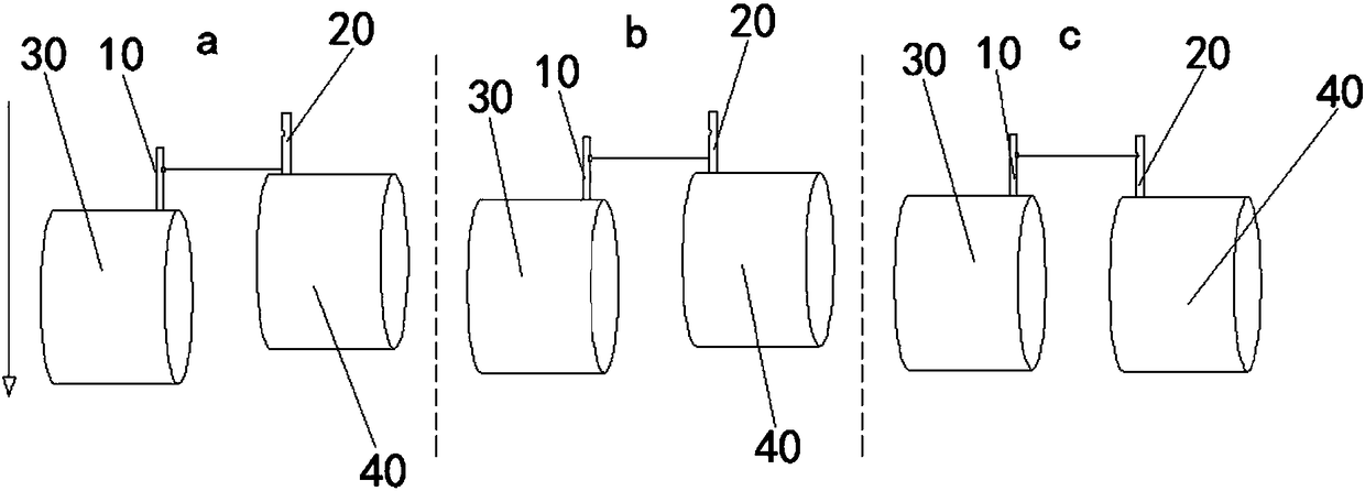
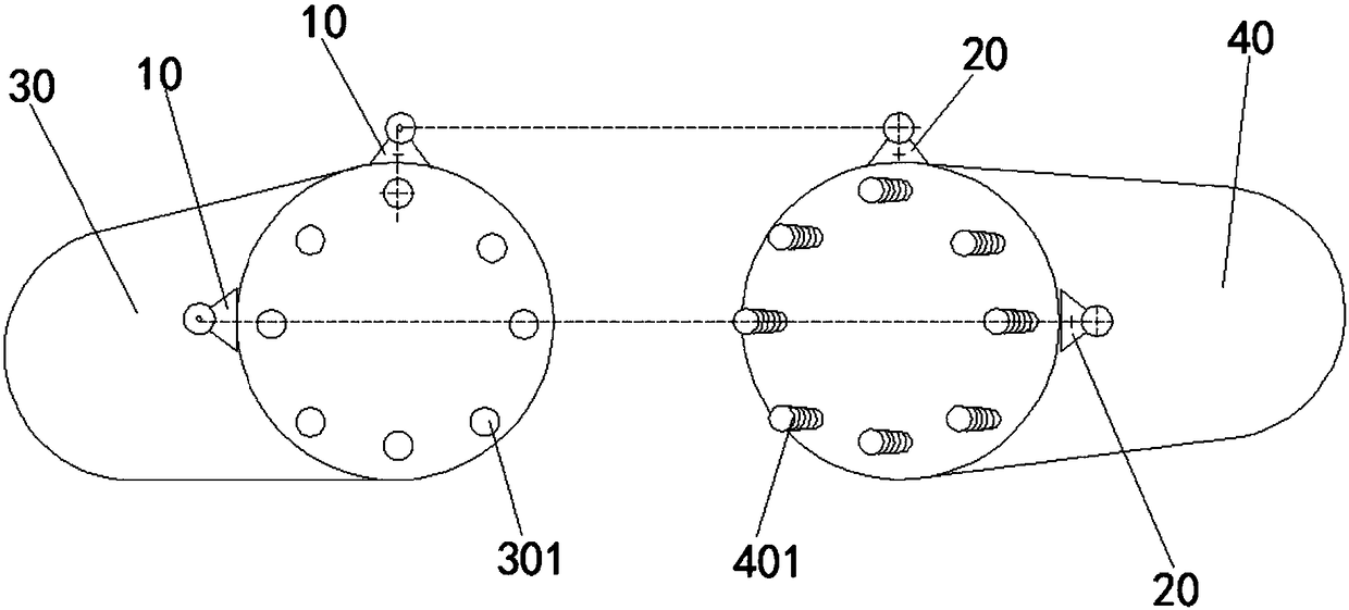
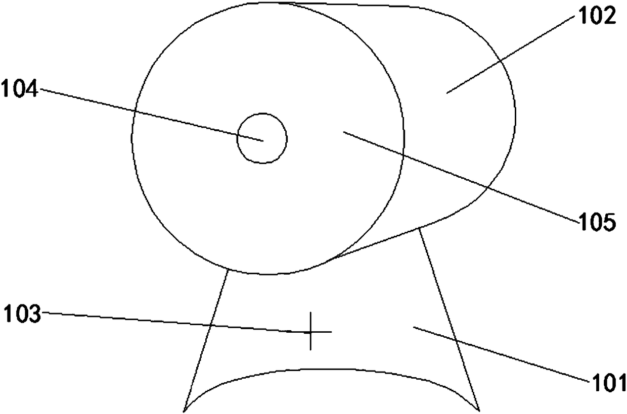
[0039] Such as Figure 1-Figure 5As shown, the precise laser alignment device for GIS equipment provided in this embodiment includes a laser emitting device 10 and a corresponding laser receiving device 20;

[0040] At least one laser emitting device 10 is arranged in the circumferential direction of the reference bus barrel 30, at least one of the laser receiving devices 20 is arranged in the circumferential direction of the moving bus barrel 40, the laser emitting device 10 and the laser receiving device 20 The number is the same, and the laser receiving device 20 is provided with an indicator light 201;

[0041] Such as figure 1 As shown, when the reference bus barrel 30 and the moving bus barrel 40 are docked, the laser emitting device 10 emits laser light, and the laser receiving device 20 can read the relative position of the moving bus barrel 40 in real time according to the received laser light. The deviation position of the reference bus barrel 30, the moving bus ba...


PUM

PropertyMeasurementUnit
Diameteraaaaaaaaaa
Diameteraaaaaaaaaa

Abstract

The invention relates to the technical field of GIS equipment and particularly relates to an accurate laser alignment device for the GIS equipment. The accurate laser alignment device comprises laseremission devices and laser reception devices, wherein at least one laser emission device is circumferentially arranged at a reference bus cylinder, at least one laser reception device is circumferentially arranged at a mobile bus cylinder, the laser reception devices are provided with indicating lamps, when the reference bus cylinder and the mobile bus cylinder are in butt joint, the laser emission devices emit laser, the deviation position of the mobile bus cylinder relative to the reference bus cylinder can be read by the laser reception devices according to the received laser in real time,the mobile bus cylinder moves based on the deviation position till the laser received by the laser reception devices reaches the alignment position, the indicating lamps are lightened, and the mobilebus cylinder stops moving. The accurate laser alignment device is advantaged in that reliability is good, professional ability requirements for operators are low, butt joint stability and accuracy canbe improved, butt joint work cost is reduced, and butt joint efficiency is improved.

Description

technical field [0001] The invention relates to the technical field of GIS equipment, in particular to a precise laser alignment device for GIS equipment. Background technique [0002] GIS equipment, that is, gas insulated switch combination electrical appliances, has a small footprint, less environmental impact during operation, less maintenance workload, and long service life. The utilization rate in power systems is increasing year by year. In recent years, GIS equipment has been affected by the process technology and assembly quality of the main components, resulting in a decline in insulation and causing many accidents. In the installation process, it is generally chosen to transport the packaged GIS modules of different parts to the equipment site, and then carry out the docking installation of the internal conductive rod and the busbar barrel. The current docking method mostly uses a large crane for rough alignment, and then manually judges the deviation direction an...

Claims


Application Information

Patent Timeline
IPC IPC(8): G01B11/00
CPCG01B11/00
Inventor 王铁柱高士森褚正超黄志张扬卓定明罗斐
Owner GUANGDONG POWER GRID CO LTD
Why Eureka
Try Eureka