
Pipe fitting traction rotation precision machining device

A processing device and technology for pipe fittings, which is applied in the field of pipe fitting traction and rotation precision processing devices, can solve the problems of poor processing accuracy, poor constraints, and inability to process at any position, so as to improve processing accuracy and efficiency and meet processing needs.

Active Publication Date: 2018-09-18
福建中童家居有限公司
View PDF9 Cites 4 Cited by
  • Summary
  • Abstract
  • Description
  • Claims
  • Application Information

AI Technical Summary

Problems solved by technology

[0003] Aiming at the problems of poor constraint and inability to realize arbitrary position processing in the surface processing of existing cylindrical pipe fittings, as well as the common problem of poor processing accuracy, the present invention provides a pipe fitting traction and rotation precision processing device

Method used


Image

  • Pipe fitting traction rotation precision machining device
  • Pipe fitting traction rotation precision machining device
  • Pipe fitting traction rotation precision machining device

Examples


Embodiment 1

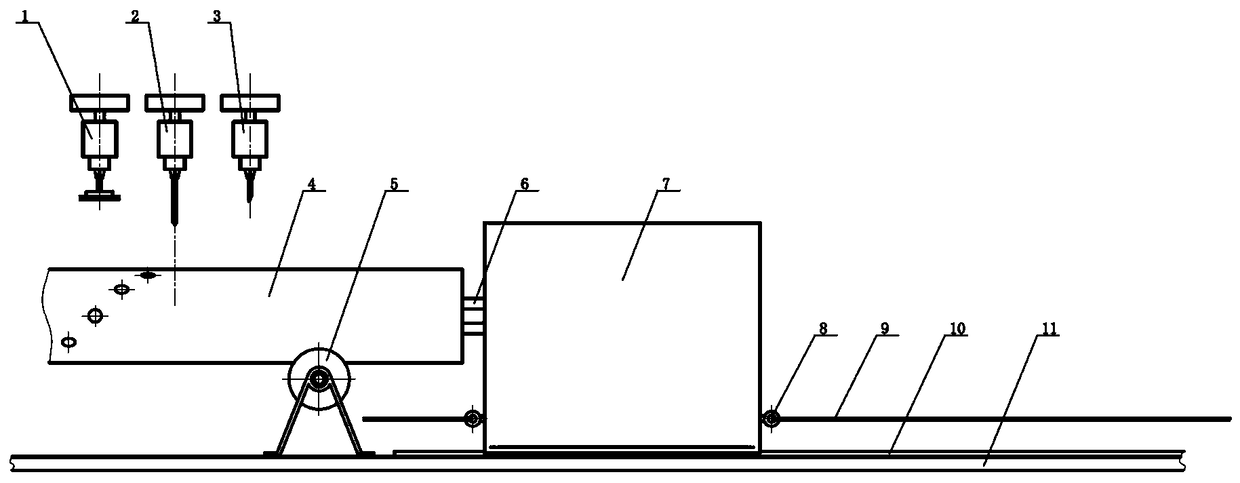
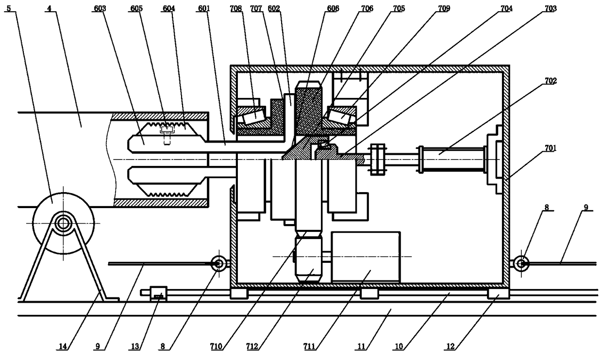
[0016] Embodiment 1: as figure 1 The pipe processing device shown has the precise effect of pulling and rotating. The device includes a pipe fitting supporting traveling mechanism, a pipe fitting processing mechanism, a pipe fitting fixing traction mechanism and the like.

[0017] Wherein, the pipe supporting traveling mechanism is that a V-shaped support roller 5 is installed on the support 11 through the support roller fixing seat 14, and the pipe fittings are matched and clamped in the V-shaped grooves of multiple groups of V-shaped support rollers 5 . Each V-shaped idler 5 can rotate and support along with the translation of the pipe.

[0018] A translation guiding mechanism is arranged between the clamping and rotating mechanism 7 and the bracket 11 , and the pulling mechanism is fixed on the bracket 11 and connected with the clamping and rotating mechanism 7 . The translation guiding mechanism is that the rail 10 along the axial direction is fixed on the bracket 11 thr...

Embodiment 2

[0025] Embodiment 2: On the basis of Embodiment 1, each inner fixture 6 is provided with a return structure. For example, a clamping groove is provided outside the clamping axial rod 601 of each internal clamping clamp 6 and a ring-shaped shrinking spring is sleeved therein. Alternatively, a clamp radial rod 602 of each inner clamp 6 is sleeved with a compression spring capable of contracting inward, and the outer end of the compression spring is supported in a corresponding block or spring seat on the rotating body 706 .

Embodiment 3

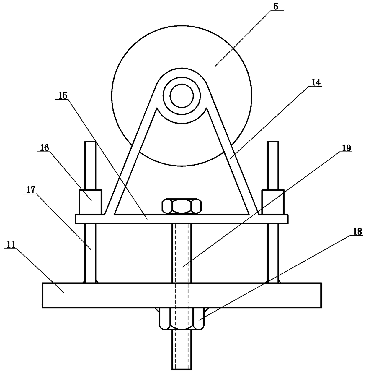
[0026] Embodiment 3: On the basis of Embodiment 1, the fixing seat of the V-shaped supporting wheel 5 is provided with a height adjustment structure, and its purpose is to meet the processing requirements of cylindrical pipe fittings with different diameters. For the cylindrical pipe fittings 4 with different diameters, since the height of the shaft center is different, the purpose of adjusting the height of the shaft center of the pipe fittings with different diameters is achieved by adjusting the support height of the V-shaped support roller 5 . see image 3As shown, the height adjustment structure of the supporting wheel fixing seat 14 is that a movable base 15 is provided on the lower side of the supporting wheel fixing seat 14, and the four corners of the movable base 15 are respectively fixed with vertical guide pipes 16, and at the same time, corresponding positions on the bracket 11 Four vertical guide rods 17 are fixed, and each guide rod 17 is matched and sleeved in ...


PUM


Abstract

The invention discloses a pipe fitting traction rotation precision machining device. The pipe fitting traction rotation precision machining device comprises a pipe fitting supporting traveling mechanism, a pipe fitting machining mechanism and a pipe fitting fixation traction mechanism. The pipe fitting fixation traction mechanism comprises a clamping rotating mechanism, an inner clamping device and a draw-off mechanism, a horizontal movement guiding mechanism is disposed between the clamping rotating mechanism and a bracket, and the draw-off mechanism is fixed to the bracket and connected withthe clamping rotating mechanism. The end portion of a pipe fitting can be clamped and fixed through the inner clamping device, the pipe fitting can be moved to any position at will in the radial direction by means of the draw-off mechanism, and the pipe fitting can rotated at any angle as needed, so that the purpose of machining the cylindrical surface of the pipe fitting at any position can be achieved. Moreover, the machining precision and efficiency of the pipe fitting are greatly improved through clamping and the control over precise horizontal movement and precise rotation.

Description

Technical field: [0001] The invention belongs to the technical field of pipe fitting surface processing equipment, and in particular relates to a pipe fitting traction and rotation precision processing device. Background technique: [0002] The existing equipment for processing cylindrical pipe fittings has a simple structure related to the positioning part, which can only process drilling or grinding at specific positions, and cannot meet the needs of processing any position on the surface of cylindrical pipe fittings. Moreover, the existing equipment for positioning pipe fittings usually has the problem of low processing accuracy. For example, the traditional processing of cylindrical pipe fittings uses channel steel as a support to support cylindrical pipe fittings. However, due to the vibration problem of the equipment during processing, the cylindrical pipe Axial or rotational problems are unavoidable for pipe fittings. Even if positioning constraint components are used...

Claims


Application Information

Patent Timeline
Patent Type & Authority Applications(China)
IPC IPC(8): B23P23/04B23Q7/00B23B31/40
CPCB23B31/4066B23P23/04B23Q7/00
Inventor 于进策
Owner 福建中童家居有限公司
Learn More