
Circularly polarized OAM (orbital angular momentum) reflect array antenna

A technology of orbital angular momentum and reflectarray antenna, which is applied in the directions of antenna, antenna coupling, resonant antenna, etc., can solve the problem of low anti-interference ability and achieve the effect of improving anti-interference ability

Active Publication Date: 2018-09-14
XIDIAN UNIV
View PDF7 Cites 28 Cited by
  • Summary
  • Abstract
  • Description
  • Claims
  • Application Information

AI Technical Summary

Problems solved by technology

The invention generates multi-modal orbital angular momentum vortex electromagnetic waves by controlling the phase compensation of the reflective array unit. However, due to the simple structure of the radiation patch and the use of variable size compensation for phase, only linearly polarized orbital angular momentum can be realized. Vortex electromagnetic wave, low anti-interference ability

Method used


Image

  • Circularly polarized OAM (orbital angular momentum) reflect array antenna
  • Circularly polarized OAM (orbital angular momentum) reflect array antenna
  • Circularly polarized OAM (orbital angular momentum) reflect array antenna

Examples


Embodiment Construction

[0025] Below in conjunction with accompanying drawing and specific embodiment, the present invention is described in further detail:

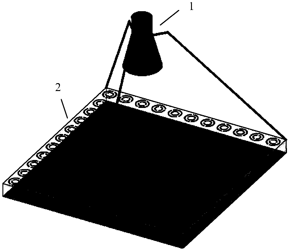
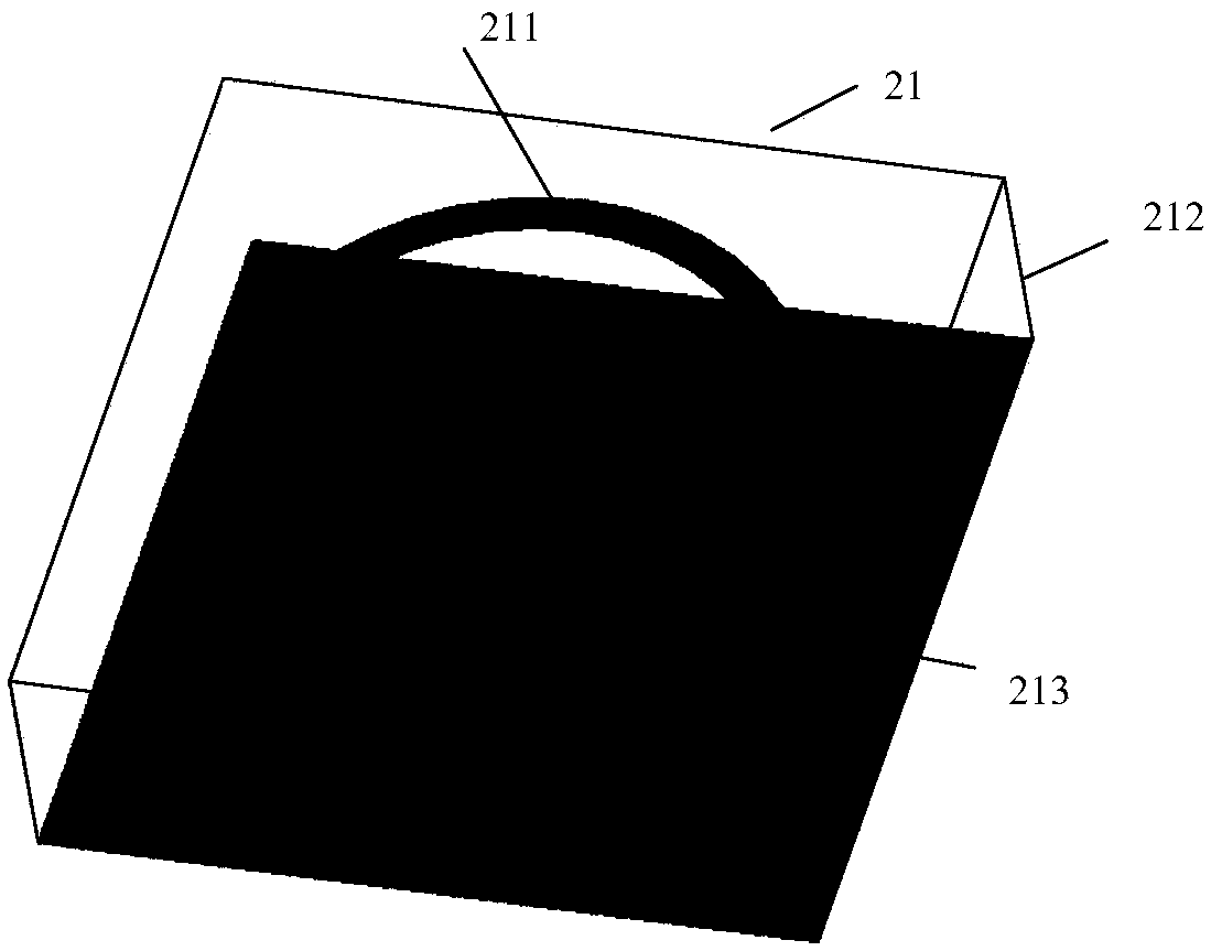
[0026] refer to figure 1 , a circularly polarized orbital angular momentum reflectarray antenna proposed by the present invention, including a feed antenna unit 1 and a reflector 2, the reflector 2 includes 11×11 radiating units 21 arranged at regular intervals, and its overall size It is 110mm×110mm×8mm, and the radiation unit 21 includes a dielectric material board 212, and a radiation patch 211 printed on one side of the dielectric material board 212 and a metal floor 213 on the other side, wherein the dielectric material board 212 adopts a square plate, and its The geometric center is coaxial with the geometric center of the radiation patch 211 .

[0027] The feed antenna unit 1 adopts a circular horn antenna. In order to radiate circularly polarized beams, the opening surface of the circular waveguide is gradually expanded. The opening ra...


PUM


Abstract

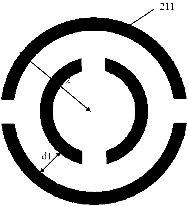
The invention provides a circularly polarized OAM (orbital angular momentum) reflect array antenna. The circularly polarized OAM reflect array antenna is used for improving interference rejection of the antenna and comprises a feed source antenna unit and a reflector, wherein the feed source antenna unit adopts a circularly polarized antenna, the radiation direction of the feed source antenna unitfaces one side, where a radiation patch is printed, of each dielectric material on the reflector, and the feed source antenna is fixed relative to the reflector; the reflector comprises N*N radiationunits which are arranged equidistantly and periodically, N is larger than or equal to 2, each radiation unit comprises a dielectric material plate, the radiation patch printed on one side surface ofthe dielectric material plate and a metal floor arranged on the other side surface, the phase of each radiation unit is determined according to a phase compensation formula of the circularly polarizedOAM reflect array antenna, and compensation of each phase is realized by a rotating unit; each radiation patch comprises two concentric ring patches, a pair of rectangular gaps are formed in an axispassing through the circle center of each ring patch, and an antenna phase shift curve is controlled by adjusting radius of each outer ring patch.

Description

technical field [0001] The invention belongs to the technical field of antennas, in particular to a circularly polarized orbital angular momentum reflection array antenna, which can be used in the technical field of wireless communication. Background technique [0002] According to the classical electrodynamic theory, electromagnetic radiation can carry not only energy but also angular momentum. The spin angular momentum SAM describing the polarization state and the orbital angular momentum OAM describing the helical phase structure together constitute the angular momentum. The orbital angular momentum Electromagnetic waves are called vortex electromagnetic waves. OAM multiplexing is a shared frequency spectrum resource technology in a common way. On the same carrier frequency, different orbital angular momentums are modulated and information is transmitted, which greatly improves the spectrum utilization efficiency and can solve the problem of spectrum resource shortage in ...

Claims


Application Information

Patent Timeline
Patent Type & Authority Applications(China)
IPC IPC(8): H01Q1/52H01Q3/30H01Q9/04
CPCH01Q1/52H01Q3/30H01Q9/0407
Inventor 李文涛孙顺莱叶秀眺张昱东史小卫
Owner XIDIAN UNIV
Learn More